ROS1 のビジョンアプリケーション
最終更新:
本章では、reComputer Jetson 上での実践的な ROS 1 ビジョンワークフローを扱います。カメラプレビュー、QR コード認識、姿勢推定、物体検出、AR マーカー、OpenCV、MediaPipe の例を含みます。
実行時間の長いサンプルは
./code/配下に、関連する図は./images/配下に保存されています。
目次
7.2.2.1 はじめにお読みください
すべては使用に関わることです。
ROS 1 環境は Docker イメージ内にあり、完全に動作させるには Docker の基盤が必要です!
注:Docker イメージでは USB カメラを使用したビジュアルケースのみ実行できます!
Docker に入る。
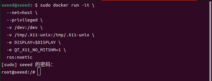
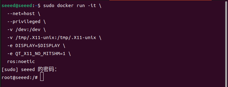
ターミナルを開き、ROS 1 用の docker イメージに対して以下のコマンドを入力します
sudo docker run -it \
  --net=host \
  --privileged \
  -v /dev:/dev \
  -v /tmp/.X11-unix:/tmp/.X11-unix \
  -e DISPLAY=$DISPLAY \
  -e QT_X11_NO_MITSHM=1 \
  ros:noetic
図
7.2.2.2 カメラプレビュー
カメラプレビュー
ROS 1 Docker イメージに入る
sudo docker run -it \
  --net=host \
  --privileged \
  -v /dev:/dev \
  -v /tmp/.X11-unix:/tmp/.X11-unix \
  -e DISPLAY=$DISPLAY \
  -e QT_X11_NO_MITSHM=1 \
  ros:noetic
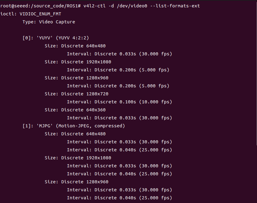
カメラがサポートするパラメーターを表示する
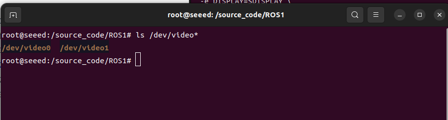
以下のコマンドを入力して、USB カメラマップのデバイス名を確認します:
ls /dev/video*対応するデバイスインデックス番号(0 から n)に応じて、USB カメラがサポートするストリーム形式、フレーム数、解像度を確認します:
# Install v4l2 utilities if they are not already installed:
apt update
apt install v4l-utils ffmpegv4l2-ctl -d /dev/video0 --list-formats-extカメラプレビュー画像 -- ターミナルコマンド
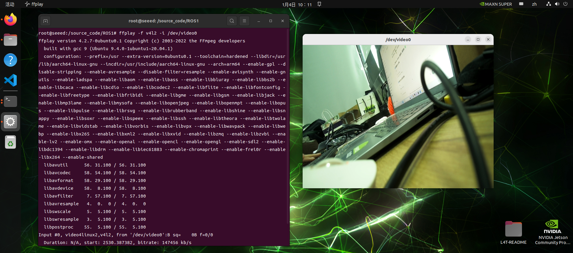
ターミナルは ffplay で USB カメラを開くことができます
ffplay -f v4l2 -i /dev/video0カメラプレビュー - Python スクリプト
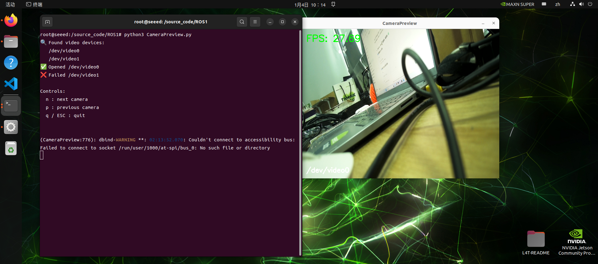
ローカルの USB カメラを使ってスクリプトをテストします:
 cd source_code/ROS 1/
 python3 CameraPreview.py
スクリプトは利用可能な USB カメラを順に処理し、表示とフレームレートの出力を行います
CameraPreview.py のソースコードは以下の通りです:
コードファイル:7-2-2-2-camera-preview-CameraPreview.py
#!/usr/bin/env python3
import cv2
import glob
import time
import os

def list_video_devices():
    """Return the /dev/video* device list."""
    devs = sorted(glob.glob("/dev/video*"))
    return devs

def try_open_camera(dev):
    """Try to open a camera device."""
    cap = cv2.VideoCapture(dev, cv2.CAP_V4L2)
    if not cap.isOpened():
        cap.release()
        return None
    return cap

def main():
    devices = list_video_devices()
    if not devices:
        print("❌ No /dev/video* found")
        return

    print("🔍 Found video devices:")
    for d in devices:
        print("  ", d)

    cams = []
    for dev in devices:
        cap = try_open_camera(dev)
        if cap:
            print(f"✅ Opened {dev}")
            cams.append((dev, cap))
        else:
            print(f"❌ Failed {dev}")

    if not cams:
        print("❌ No usable cameras")
        return

    cam_index = 0
    last_time = time.time()
    fps = 0.0

    print("\nControls:")
    print("  n: next camera")
    print("  p: previous camera")
    print("  q / ESC: quit\n")

    while True:
        dev, cap = cams[cam_index]

        ret, frame = cap.read()
        if not ret:
            cv2.putText(
                frame,
                "Camera read failed",
                (30, 50),
                cv2.FONT_HERSHEY_SIMPLEX,
                1,
                (0, 0, 255),
                2,
            )
        else:
            now = time.time()
            fps = 1.0 / (now - last_time)
            last_time = now

            # FPS display
            cv2.putText(
                frame,
                f"FPS: {fps:.2f}",
                (20, 40),
                cv2.FONT_HERSHEY_SIMPLEX,
                1,
                (0, 255, 0),
                2,
            )

            # Device name display
            cv2.putText(
                frame,
                dev,
                (20, frame.shape[0] - 20),
                cv2.FONT_HERSHEY_SIMPLEX,
                0.7,
                (255, 255, 255),
                2,
            )

        cv2.imshow("CameraPreview", frame)

        key = cv2.waitKey(1) & 0xFF
        if key in [27, ord("q")]:  # ESC / q
            break
        elif key == ord("n"):
            cam_index = (cam_index + 1) % len(cams)
            print(f"➡ Switch to {cams[cam_index][0]}")
            time.sleep(0.2)
        elif key == ord("p"):
            cam_index = (cam_index - 1) % len(cams)
            print(f"⬅ Switch to {cams[cam_index][0]}")
            time.sleep(0.2)

    for _, cap in cams:
        cap.release()
    cv2.destroyAllWindows()

if __name__ == "__main__":
    main()
図

7.2.2.3 QR コード
1. QR コードの紹介
QR コードは二次元バーコードの一種であり、QR は英語の「Quick Response」の頭字語で、迅速な応答を意味し、発明者が QR コードを素早くデコードできるようにと願ったことに由来します。QR コードは情報容量が大きく、信頼性が高く、低コストであるだけでなく、漢字や画像などの多様なテキスト情報を機密かつ改ざんしにくい形で扱いやすいという特長も持っています。さらに重要なことに、QR コード技術はオープンソースです。
QR の紹介
QR コードの特徴
QR コード内のデータ値には重複情報(冗長値)が含まれています。そのため、二次元コード構造の最大 30% が破損しても、二次元コードの可読性には影響しません。QR コードの記憶容量は最大 7089 ビット、または 4296 文字(句読点や特殊文字を含む)にも及び、すべて QR コードに書き込むことができます。数字や文字だけでなく、単語やフレーズ(ウェブサイトなど)もエンコードすることが可能です。QR コードに追加されるデータが増え、コードのサイズが大きくなるほど、コード構造はより複雑になります。
QR 2次元コードの作成と認識
インストールの依存関係:
コードファイル:7-2-2-3-qr-codes-install-deps.sh
sudo apt update
sudo apt install -y python3-pip libzbar-dev
python3 -m pip install qrcode pyzbar
qrcode オブジェクトを作成します。ディレクトリ内で qr code create.py スクリプトを直接実行できます:
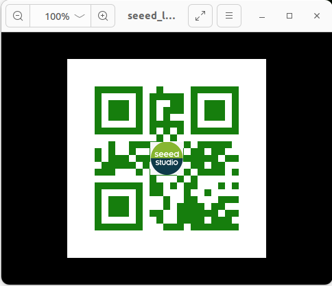
python3 qrcode_create.py作業ディレクトリの figure フォルダーに、設定したロゴ付きの二次元コード(QR コード)が生成されます。プリセットのロゴ画像の場所も figure フォルダー内にあります。生成される二次元コードの効果は以下の通りです:
qrcode create.py のソースコードは以下の通りです:
コードファイル:7-2-2-3-qr-codes-create.py
#!/usr/bin/env python3
import os
import qrcode
from PIL import Image
from pathlib import Path


def add_logo(img, logo_path):
    # Add logo, open logo image
    icon = Image.open(    logo_path)
    img_w, img_h = img.size
    # Set the size of the logo
    factor = 6
    size_w = int(img_w / factor)
    size_h = int(img_h / factor)
    icon_w, icon_h = icon.size
    if icon_w > size_w: icon_w = size_w
    if icon_h > size_h: icon_h = size_h
    # Resize the logo
    icon = icon.resize((icon_w, icon_h), Image.Resampling.LANCZOS)
    # Center the logo
    w = int((img_w - icon_w) / 2)
    h = int((img_h - icon_h) / 2)
    # Paste the logo
    img.paste(icon, (w, h), mask=None)
    return img


def create_qrcode(data, file_name, logo_path):
    '''
    version: Integer from 1 to 40, controls the size of the QR code.
    error_correction: Controls the error correction function. Can be one of the following:
        ERROR_CORRECT_L: About 7% or fewer errors can be corrected.
        ERROR_CORRECT_M (default): About 15% or fewer errors can be corrected.
        ERROR_CORRECT_H: About 30% or fewer errors can be corrected.
    box_size: Controls the number of pixels in each box of the QR code.
    border: Controls the number of boxes for the border (the default is 4).
    '''
    qr = qrcode.QRCode(
        version=1,
        error_correction=qrcode.constants.ERROR_CORRECT_H,
        box_size=10,
        border=4)
    # Add data to the QR code
    qr.add_data(data)
    print(data)
    qr.make(fit=True)
    img = qr.make_image(fill_color="green", back_color="white")
    # Add logo if file exists
    if Path(logo_path).is_file():
        img = add_logo(img, logo_path)
    # Save and show the image
    img.save(file_name)
    img.show()
    return img


if __name__ == '__main__':
    file_path = "./figures"
    logo_path = file_path + "/seeed_logo.png"
    out_img = file_path + '/seeed_logo_qr.jpg'
    text = input("Please enter:")
    create_qrcode(text, out_img, logo_path)
QR コードを作成するパラメーターの意味は以下の通りです:
コードファイル:7-2-2-3-qr-codes-example-03.py
'''
    Parameters:
    version:integer from 1 to 40 that controls QR-code size.
             use None with fit if you want the library to choose automatically.
    error_correction:controls QR-code error correction.
    ERROR_CORRECT_L:about 7% or fewer errors can be corrected.
    ERROR_CORRECT_M (default): about 15% or fewer errors can be corrected.
    ROR_CORRECT_H:about 30% or fewer errors can be corrected.
    box_size:controls the pixel size of each QR-code cell.
    border:controls the border width in cells; the default 4 is the standard minimum.
    '''
二次元コードを生成したら、それを印刷して(A4 サイズで十分です)二次元認識テストを行うことができます。
認識機能のコードセグメントは以下の通りです:
コードファイル:7-2-2-3-qr-codes-example-04.py
def decodeDisplay(image, font_path):
    gray = cv.cvtColor(image, cv.COLOR_BGR2GRAY)
    # Convert decoded text to Unicode before drawing it on the image.
    barcodes = pyzbar.decode(gray)
    for barcode in barcodes:
        # Extract the QR code bounding box.
        (x, y, w, h) = barcode.rect
        # Draw the barcode bounding box on the image.
        cv.rectangle(image, (x, y), (x + w, y + h), (225, 0, 0), 5)
        encoding = 'UTF-8'
        # Convert the decoded bytes to a string before drawing.
        barcodeData = barcode.data.decode(encoding)
        barcodeType = barcode.type
        # Draw the decoded data and type on the image.
        pilimg = Image.fromarray(image)
        # Create a drawing object.
        draw = ImageDraw.Draw(pilimg)
        # Parameter 1: font file path. Parameter 2: font size.
        fontStyle = ImageFont.truetype(font_path, size=12, encoding=encoding)
        # Parameter 1: text position. Parameter 2: text. Parameter 3: text color. Parameter 4: font.
        draw.text((x, y - 25), str(barcode.data, encoding), fill=(255, 0, 0), font=fontStyle)
        # Convert the PIL image back to an OpenCV image.
        image = cv.cvtColor(np.array(pilimg), cv.COLOR_RGB2BGR)
        # Print barcode data and type to the terminal.
        print("[INFO] Found {} barcode: {}".format(barcodeType, barcodeData))
    return image
QR コード認識ディレクトリで、二次元コードの検出を開始します:
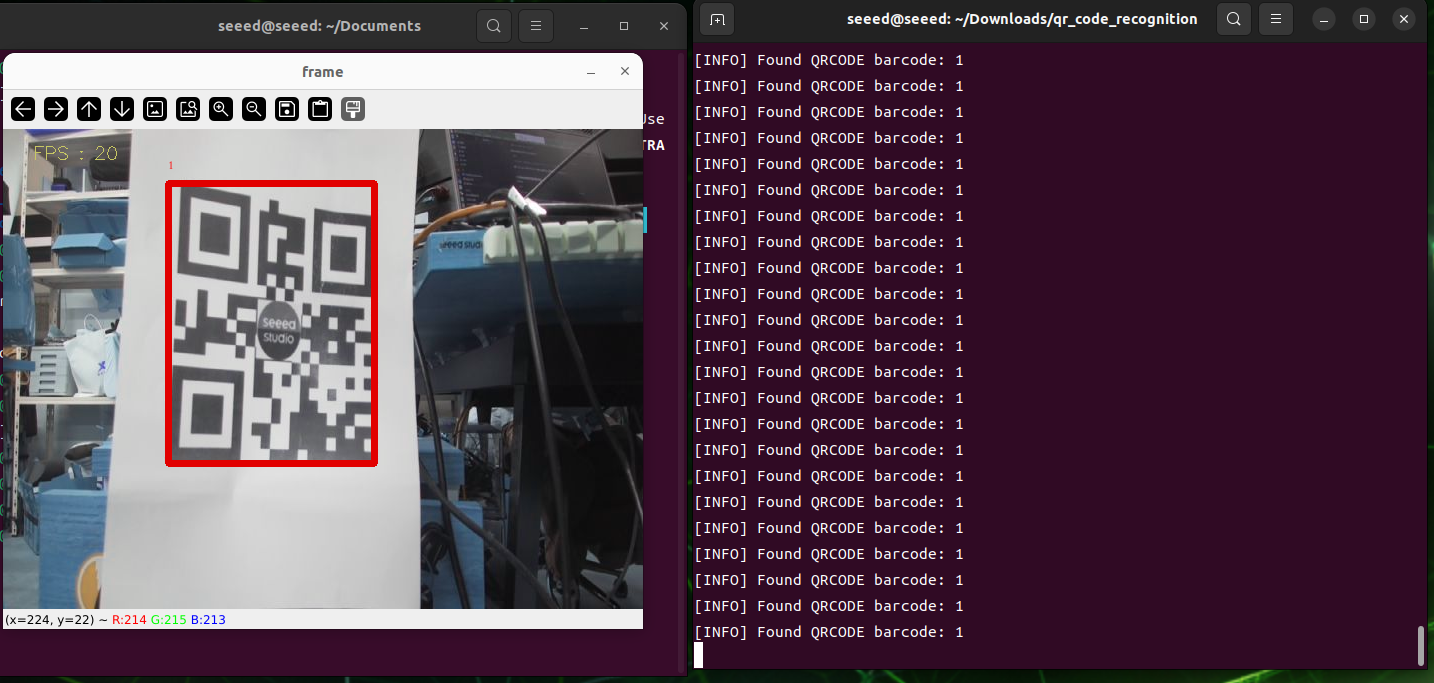
qrcode_parsing_usb.pyテスト結果は以下の図の通りで、二次元コードが認識されるとテスト枠が描画されます。
図
7.2.2.4 人体姿勢推定
人体姿勢推定
はじめに
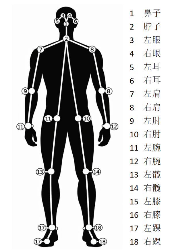
人体姿勢評価は、画像や動画を通じて人体の主要な関節の位置を自動的に識別・特定し、人体の骨格構造をモデル化するために設計された、コンピューターベースの視覚技術です。人体姿勢推定は、動作認識、インテリジェント監視、人間とのインタラクション、モーション解析、リハビリテーション、バーチャルリアリティなどの分野で広く応用されており、「人体を見る」ことと「人間の行動を理解する」ことをつなぐ重要な技術です。
II. 原理
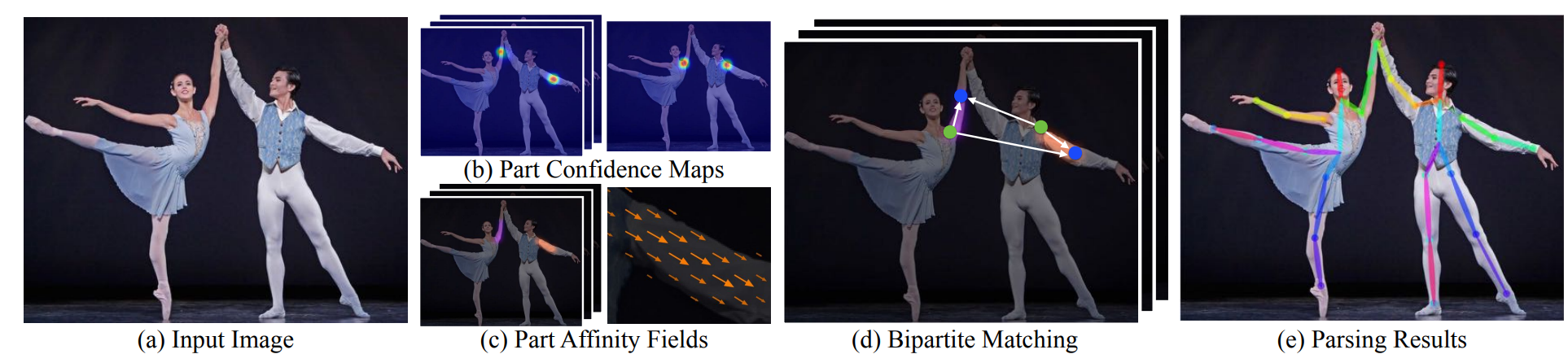
まず、入力された人体画像は畳み込みニューラルネットワーク(CNN)に送られて特徴抽出が行われ、高レベルの意味的特徴が得られます。次にネットワーク構造は 2 つの分岐に分けられ、一方は Part Confidence Maps(キーポイント信頼度マップ)を予測し、個々の人体関節の空間上の位置の確率分布を示します。もう一方は Part Affinity Fields(PAF、身体関連フィールド)を予測し、異なる関節間のリンクと方向情報をベクトル形式で記述します。候補ノードを検出する信頼度マップに基づき、PAF が提供する方向の一貫性情報を利用して、ノード間の接続をグラフ上の二部マッチング問題としてモデル化し、同一人物に属する関節ノードを正しくマッチングすることで、完全な人体骨格を段階的に構築します。さらに、複数人の姿勢推定は Multi-Person Parsing 問題とみなすことができ、複数点の接続をグラフマッチング問題に変換し、ハンガリアン法(Hungarian Algorithm)などの古典的な二次元マッチング手法を用いて最適な関節ノードの組み合わせを見つけることで、複数の人体姿勢の正確かつ安定した推定を実現します。
手続きの開始
ROS 1 docker イメージへのアクセス
sudo docker run -it \
  --net=host \
  --privileged \
  -v /dev:/dev \
  -v /tmp/.X11-unix:/tmp/.X11-unix \
  -e DISPLAY=$DISPLAY \
  -e QT_X11_NO_MITSHM=1 \
  ros:noetic
インストールの依存関係
apt-get update
apt-get install -y libatlas-base-dev libprotobuf-dev protobuf-build
apt-get install python3-pip
pip install \
  https://files.pythonhosted.org/packages/c0/b7/20228024ef7bcfaa9cad2cb2514f3f7cc7a2c2c16715dc65cb01c793693c/mediapipe-0.10.9-cp38-cp38-manylinux_2_17_aarch64.manylinux2014_aarch64.whl

# Check whether the installation succeeded.
python3 -c "import mediapipe as mp; print(mp.__version__)"
画像を用いた推論
コードファイルのディレクトリに入り、コードスクリプトを実行します
cd sources_code/ROS 1
python3 target_pose_img.py
動画像を用いた推論
コードスクリプトを実行します
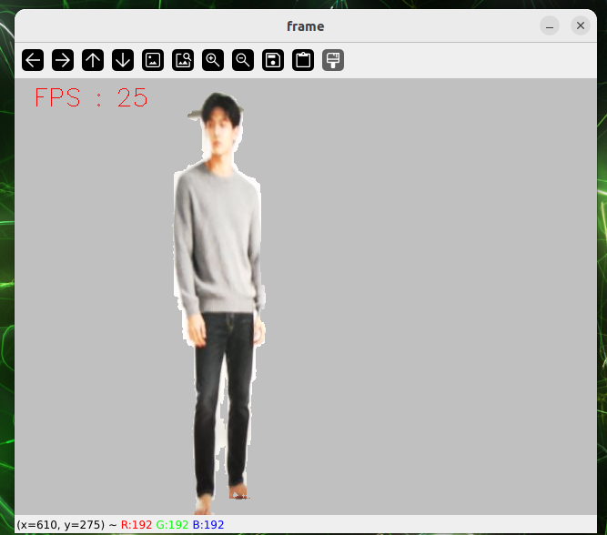
undefined図

7.2.2.5 物体検出
物体検出
深層学習において、物体検出(Target Detection)はコンピュータービジョンの中核的なタスクの一つであり、画像内のすべての関心対象を識別しマーキングすることを目的としています。一般的な手法は主に次の 2 つに分類されます:
2 段階検出: 代表的な手法には R-CNN、Fast R-CNN、Fast R-CNN があります。Mr. Region Products の後、各候補領域を分類して回帰します。これらの手法は精度が高い一方で、比較的低速であり、高精度が求められるシナリオに適しています。
1 段階検出: 代表的な手法には YOLO(You Only Look Once)、SSD(Single Shot MultiBox Detector)があります。候補領域を生成する必要なく、特徴マップ上でオブジェクトのカテゴリと境界枠を直接予測するため、リアルタイム検出に適した高速な処理が可能ですが、初期の精度は 2 段階検出よりもやや劣ります。
本節では、OpenCV の dnn モジュールを使用して物体検出を実現する方法を説明します
プログラムの開始
画像による推論
コードディレクトリに移動し、スクリプトを実行します
cd sources_code/ROS 1
python3 target_detect_img.py
論理カメラ
コードディレクトリに移動し、スクリプトを実行します
cd sources_code/ROS 1
python3 target_detect_video.py
7.2.2.6 AR ビジョン
AR ビジュアル
拡張現実(AR、Augmented Reality)とは、コンピューターベースの視覚技術を用いて、仮想情報や 3D モデルを現実世界の画像や動画にリアルタイムで重ね合わせ、環境に対するユーザーの知覚とインタラクション体験を強化することを指します。実際のシーンの映像キャプチャに、物体検出、特徴点トラッキング、深度推定などの技術を組み合わせることで、仮想物体と現実世界との空間的な位置合わせとリアルタイムのインタラクションを実現し、娯楽、工業デザイン、教育トレーニング、ナビゲーションなどの分野で幅広く利用されています。
ROS 1 Docker イメージに入る
sudo docker run -it \
  --net=host \
  --privileged \
  -v /dev:/dev \
  -v /tmp/.X11-unix:/tmp/.X11-unix \
  -e DISPLAY=$DISPLAY \
  -e QT_X11_NO_MITSHM=1 \
  ros:noetic
カメラのマーキング。
ROS は公式にカメラキャリブレーションパッケージを提供しており、USB カメラを簡単にマーキングできます:
apt install ros-noetic-camera-calibration
apt install ros-noetic-usb-cam
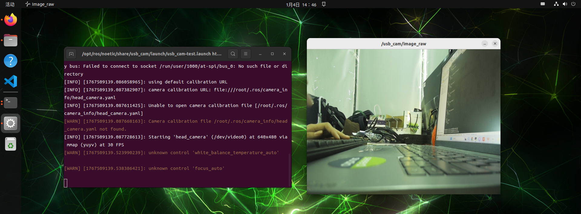
USB カメラノードの起動
roslaunch usb_cam usb_cam-test.launchパレットの準備
A4 サイズのタブレットをダウンロードして印刷します
マーキングノードの開始
ROS 1 用の docker イメージで別のターミナルを開き、マーキングノードを実行します
sudo docker run -it \
  --net=host \
  --privileged \
  -v /dev:/dev \
  -v /tmp/.X11-unix:/tmp/.X11-unix \
  -e DISPLAY=$DISPLAY \
  -e QT_X11_NO_MITSHM=1 \
  ros:noetic

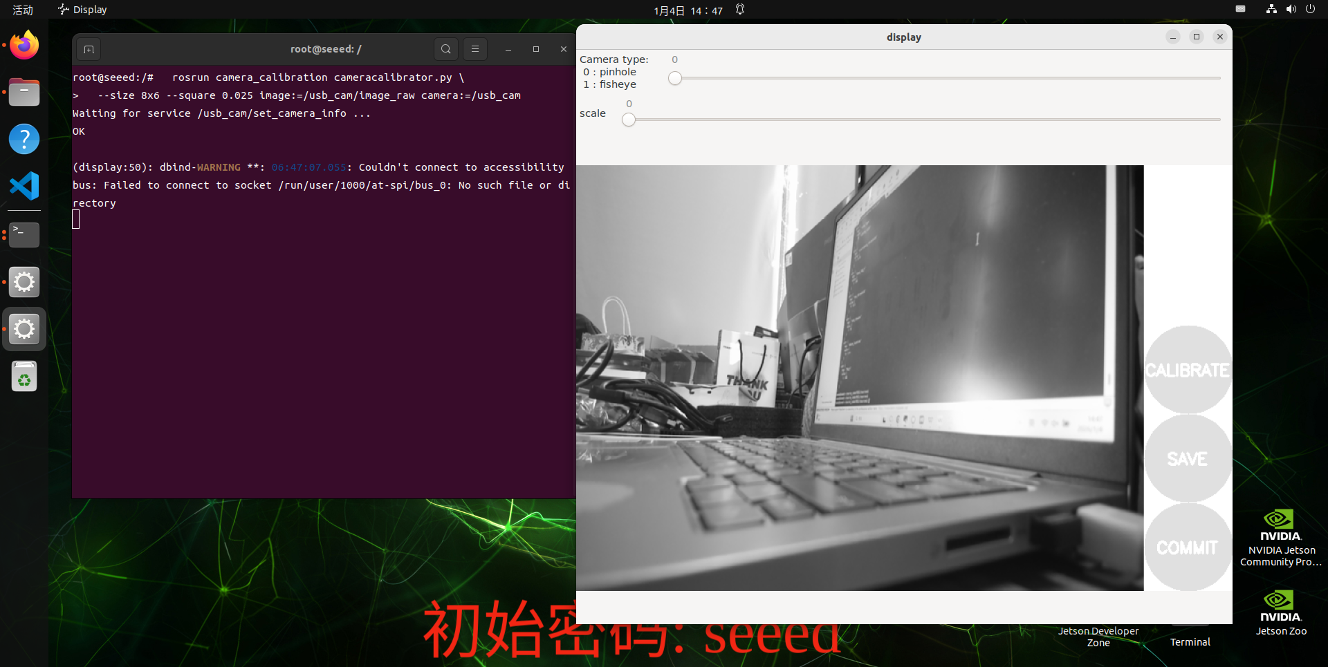
  rosrun camera_calibration cameracalibrator.py \
  --size 8x6 --square 0.025 image:=/usb_cam/image_raw camera:=/usb_cam
パラメーターの説明:
--size 8x6:内角の数(列 x 行)(8x6 = 9x7 グリッドの 48 個の角)
--square 0.025:正方形一辺の長さ、単位 m(24mm)
画像トピック
camera:=/usb_cam:カメラの名前空間
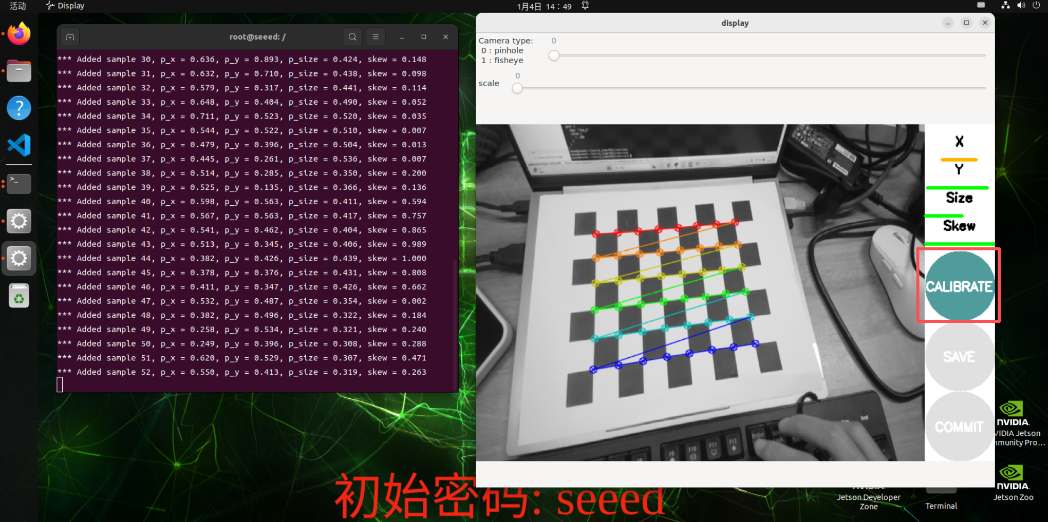
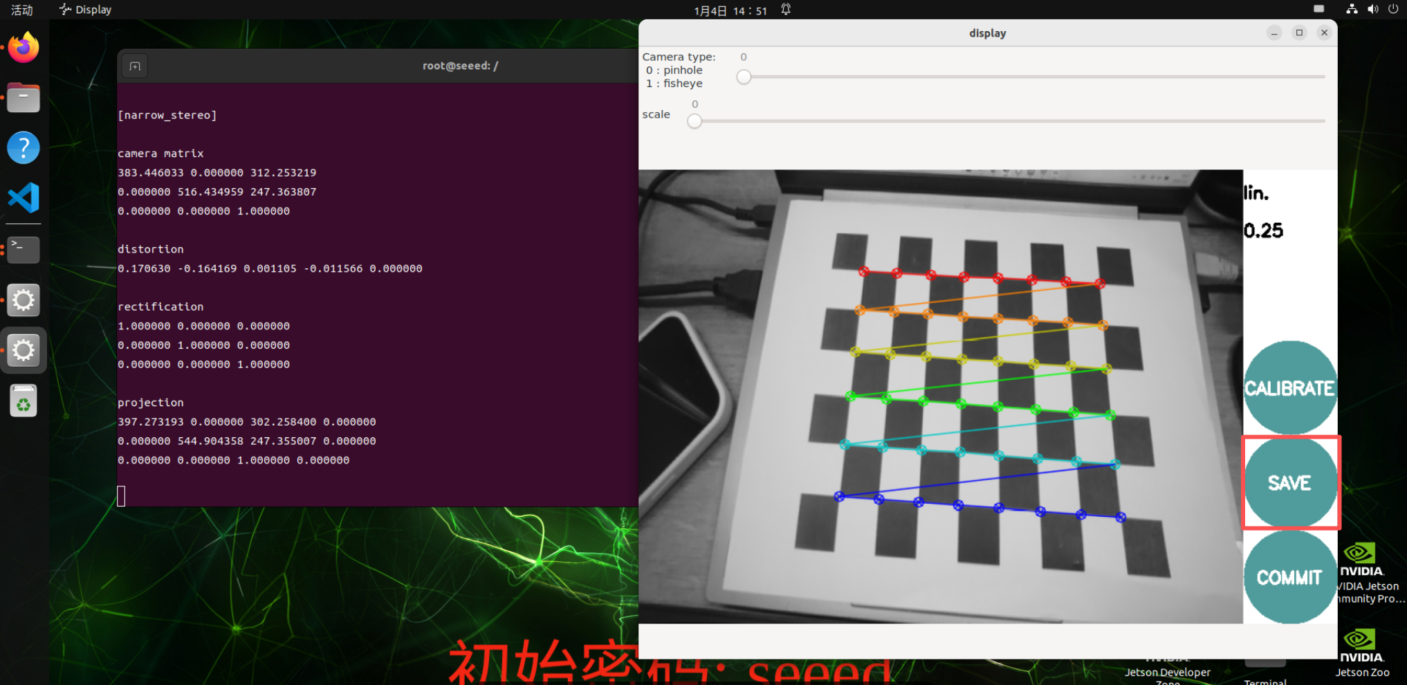
マーキングインターフェース
X:カメラビュー内でのチェスグリッドの左右の動き
Y:カメラビュー内でのチェスパネルの上下の動き
Size:カメラビュー内でのボードの前後の大きさ
Skew:カメラビュー内でのチェスパネルの傾き
正常に開始すると、ボードは画像の中央に配置され、位置を変えていきます。システムは自動的に認識を行い、X、Y、Size、Skew の下にあるラインが、赤から黄色までのデータ収集でできるだけ多く埋まっている状態が最も良いとされます。
Calibrate をクリックしてカメラの内部パラメーターを計算します。インターフェースは無反応に見えることがありますが、ターミナルには出力があるため、待ってください!
計算が成功すると、ターミナルにカメラのパラメーターが表示されるので、SAVE をクリックしてカメラパラメーターを保存します。
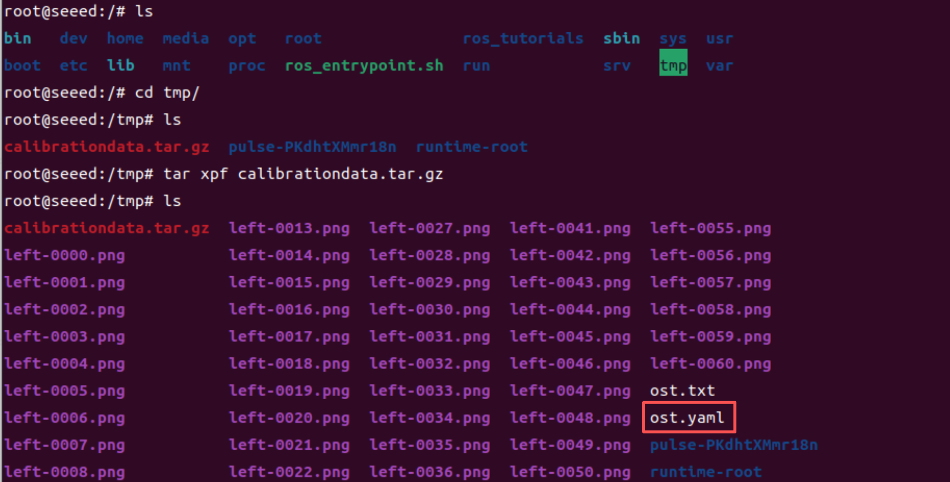
結果はデフォルトで /tmp/calibrationdata.tar.gz に保存されます
それを展開し、tag parameters. yaml ファイルをスクリプトコードディレクトリに移動します
mv tmp/ost.yaml /source_code/ROS 1/sourcesスクリプトの実行
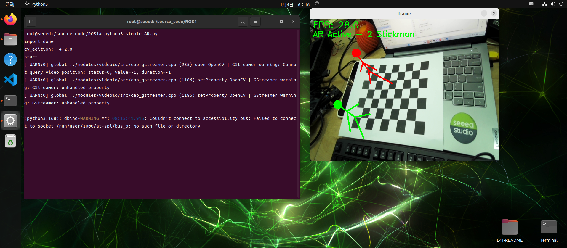
ROS 1 Docker コンテナ内で AR スクリプトを実行します:
python3 simple_AR.pyコードファイル:7-2-2-6-ar-vision-example-01.py
#!/usr/bin/env python3
# simple_AR.py
# common lib
import os
import sys
import time
import cv2 as cv
import numpy as np
import yaml

print("import done")

cv_edition = cv.__version__
print("cv_edition: ",cv_edition)

def load_camera_from_ost(yaml_path: str):
    with open(yaml_path, 'r') as f:
        params = yaml.safe_load(f)
    camera_data = params['camera_matrix']['data']
    dist_data = params['distortion_coefficients']['data']
    camera_matrix = np.array(camera_data, dtype=np.float32).reshape(3, 3)
    dist_coeffs = np.array(dist_data, dtype=np.float32).reshape(-1, 1)
    return camera_matrix, dist_coeffs

def draw_stickman(img, img_pts):
    cv.line(img, tuple(img_pts[18]), tuple(img_pts[4]), (0, 0, 255), 3)
    cv.line(img, tuple(img_pts[18]), tuple(img_pts[6]), (0, 0, 255), 3)
    cv.line(img, tuple(img_pts[18]), tuple(img_pts[21]), (0, 0, 255), 3)
    cv.line(img, tuple(img_pts[21]), tuple(img_pts[19]), (0, 0, 255), 3)
    cv.line(img, tuple(img_pts[21]), tuple(img_pts[20]), (0, 0, 255), 3)
    cv.line(img, tuple(img_pts[21]), tuple(img_pts[22]), (0, 0, 255), 3)
    cv.circle(img, tuple(img_pts[22]), 15, (0, 0, 255), -1)
    cv.line(img, tuple(img_pts[74]), tuple(img_pts[72]), (0, 255, 0), 3)
    cv.line(img, tuple(img_pts[74]), tuple(img_pts[73]), (0, 255, 0), 3)
    cv.line(img, tuple(img_pts[74]), tuple(img_pts[37]), (0, 255, 0), 3)
    cv.line(img, tuple(img_pts[37]), tuple(img_pts[76]), (0, 255, 0), 3)
    cv.line(img, tuple(img_pts[37]), tuple(img_pts[77]), (0, 255, 0), 3)
    cv.line(img, tuple(img_pts[37]), tuple(img_pts[75]), (0, 255, 0), 3)
    cv.circle(img, tuple(img_pts[75]), 15, (0, 255, 0), -1)
    return img

def main():
    print("start")

    pattern_size = (8,6)
    yaml_path = os.path.join(os.path.dirname(__file__), 'sources', 'ost.yaml')
    camera_matrix, dist_coeffs = load_camera_from_ost(yaml_path)

    object_points = np.zeros((pattern_size[0] * pattern_size[1], 3), np.float32)
    object_points[:,:2] = np.mgrid[0:pattern_size[0], 0:pattern_size[1]].T.reshape(-1, 2)

    axis = np.float32([
            [0, 0, -1], [0, 8, -1], [5, 8, -1], [5, 0, -1],
            [1, 2, -1], [1, 6, -1], [4, 2, -1], [4, 6, -1],
            [1, 0, -4], [1, 8, -4], [4, 0, -4], [4, 8, -4],
            [1, 2, -4], [1, 6, -4], [4, 2, -4], [4, 6, -4],
            [0, 1, -4], [3, 2, -1], [2, 2, -3], [3, 2, -3],
            [1, 2, -3], [2, 2, -4], [2, 2, -5], [0, 4, -4],
            [2, 3, -4], [1, 3, -4], [4, 3, -5], [4, 5, -5],
            [1, 2, -3], [1, 6, -3], [5, 2, -3], [5, 6, -3],
            [3, 4, -5], [0, 6, -4], [5, 6, -4], [2, 8, -4],
            [3, 8, -4], [2, 6, -4], [2, 0, -4], [1, 5, -4],
            [3, 0, -4], [3, 2, -4], [0, 3, -4], [1, 2, -4],
            [4, 2, -4], [5, 3, -4], [2, 7, -4], [3, 7, -4],
            [3, 3, -1], [3, 5, -1], [1, 5, -1], [1, 3, -1],
            [3, 3, -3], [3, 5, -3], [1, 5, -3], [1, 3, -3],
            [1, 3, -6], [1, 5, -6], [3, 3, -4], [3, 5, -4],
            [0, 0, -4], [3, 1, -4], [1, 1, -4], [0, 2, -4],
            [2, 4, -4], [4, 4, -4], [0, 8, -4], [5, 8, -4],
            [5, 0, -4], [0, 4, -5], [5, 4, -4], [5, 4, -5],
            [2, 5, -1], [2, 7, -1], [2, 6, -3], [2, 6, -5],
            [2, 5, -3], [2, 7, -3]
            ])

    capture = cv.VideoCapture(0)
    if cv_edition[0] == '3':
        capture.set(cv.CAP_PROP_FOURCC, cv.VideoWriter_fourcc(*'XVID'))
    else:
        capture.set(cv.CAP_PROP_FOURCC, cv.VideoWriter.fourcc('M', 'J', 'P', 'G'))
    capture.set(6, cv.VideoWriter_fourcc('M', 'J', 'P', 'G'))
    capture.set(cv.CAP_PROP_FRAME_WIDTH, 640)
    capture.set(cv.CAP_PROP_FRAME_HEIGHT, 480)

    last_time = time.time()
    fps = 0.0

    while True:
        ret, frame = capture.read()
        if not ret:
            break

        now = time.time()
        fps = 1.0 / max(1e-6, (now - last_time))
        last_time = now
        gray = cv.cvtColor(frame, cv.COLOR_BGR2GRAY)

        retval, corners = cv.findChessboardCorners(
            gray,
            pattern_size,
            None,
            flags=cv.CALIB_CB_ADAPTIVE_THRESH + cv.CALIB_CB_NORMALIZE_IMAGE + cv.CALIB_CB_FAST_CHECK,
        )

        if retval:
            corners = cv.cornerSubPix(
                gray,
                corners,
                (11, 11),
                (-1, -1),
                (cv.TERM_CRITERIA_EPS + cv.TERM_CRITERIA_MAX_ITER, 30, 0.001),
            )
            retval, rvec, tvec, _inliers = cv.solvePnPRansac(
                object_points,
                corners,
                camera_matrix,
                dist_coeffs,
            )
            if retval:
                image_points, _jacobian = cv.projectPoints(
                    axis,
                    rvec,
                    tvec,
                    camera_matrix,
                    dist_coeffs,
                )
                img_pts = np.int32(image_points).reshape(-1, 2)
                frame = draw_stickman(frame, img_pts)

                cv.putText(frame, "AR Active - 2 Stickman", (10, 60), cv.FONT_HERSHEY_SIMPLEX, 0.9, (0, 255, 0), 2)
            else:
                cv.putText(frame, "Pose estimation failed", (10, 60), cv.FONT_HERSHEY_SIMPLEX, 0.9, (0, 0, 255), 2)
        else:
            cv.putText(frame, "No chessboard detected", (10, 60), cv.FONT_HERSHEY_SIMPLEX, 0.9, (0, 0, 255), 2)

        cv.putText(frame, f"FPS: {fps:.1f}", (10, 30), cv.FONT_HERSHEY_SIMPLEX, 1, (0, 255, 0), 2)
        cv.imshow('frame', frame)

        action = cv.waitKey(1) & 0xFF
        if action == ord('q') or action == 113:
            break

    capture.release()
    cv.destroyAllWindows()

if __name__ == "__main__":
    main()
図
7.2.2.7 OpenCV アプリケーション
OpenCV アプリケーション
Opencv apps は ROS コミュニティが保守している機能パッケージ群で、大量の OpenCV 画像処理とコンピュータービジョン機能を ROS ノードにカプセル化しており、標準トピックの入力を ROS システム内で直接呼び出すことができ、自分で OpenCV のコードを用意する必要がありません。
Opencv apps の起動
docker の起動
sudo docker run -it \
  --name ros_noetic \
  --net=host \
  --privileged \
  -v /dev:/dev \
  -v /tmp/.X11-unix:/tmp/.X11-unix \
  -e DISPLAY=$DISPLAY \
  -e QT_X11_NO_MITSHM=1 \
  ros:noetic
インストール
apt install ros-noetic-opencv-apps
apt install -y ros-noetic-usb-cam


# Check whether the installation succeeded.
roscd opencv_apps
# Open another terminal.
sudo docker exec -it ros_noetic bash

rosrun opencv_apps face_detection image:=/usb_cam/image_raw
カメラの有効化
roslaunch usb_cam usb_cam-test.launchOpencv apps の使用
一度に実行できる機能は 1 つだけです。カメラを有効化した後、以下のコマンドを実行する必要があります:
roslaunch opencv_apps face_recognition.launch image:=/usb_cam/image_raw          # Face recognition
roslaunch opencv_apps corner_harris.launch image:=/usb_cam/image_raw             # Harris corner detection
roslaunch opencv_apps camshift.launch image:=/usb_cam/image_raw                  # Object tracking
roslaunch opencv_apps contour_moments.launch image:=/usb_cam/image_raw           # Contour moments
roslaunch opencv_apps convex_hull.launch image:=/usb_cam/image_raw               # Convex hull
roslaunch opencv_apps discrete_fourier_transform.launch image:=/usb_cam/image_raw # Discrete Fourier transform
roslaunch opencv_apps edge_detection.launch image:=/usb_cam/image_raw            # Edge detection
roslaunch opencv_apps face_detection.launch image:=/usb_cam/image_raw            # Face detection
roslaunch opencv_apps fback_flow.launch image:=/usb_cam/image_raw                # Optical flow detection
roslaunch opencv_apps find_contours.launch image:=/usb_cam/image_raw             # Contour detection
roslaunch opencv_apps general_contours.launch image:=/usb_cam/image_raw          # General contour detection
roslaunch opencv_apps goodfeature_track.launch image:=/usb_cam/image_raw         # Feature point tracking
roslaunch opencv_apps hls_color_filter.launch image:=/usb_cam/image_raw          # HLS color filtering
roslaunch opencv_apps hough_circles.launch image:=/usb_cam/image_raw             # Hough circle detection
roslaunch opencv_apps hough_lines.launch image:=/usb_cam/image_raw               # Hough line detection
roslaunch opencv_apps hsv_color_filter.launch image:=/usb_cam/image_raw          # HSV color filtering
roslaunch opencv_apps lk_flow.launch image:=/usb_cam/image_raw                   # LKoptical flow algorithm
roslaunch opencv_apps people_detect.launch image:=/usb_cam/image_raw             # People detection
roslaunch opencv_apps phase_corr.launch image:=/usb_cam/image_raw                # Phase correlation displacement detection
roslaunch opencv_apps pyramids.launch image:=/usb_cam/image_raw                  # Image pyramid
roslaunch opencv_apps rgb_color_filter.launch image:=/usb_cam/image_raw          # RGB color filtering
roslaunch opencv_apps segment_objects.launch image:=/usb_cam/image_raw           # Foreground segmentation
roslaunch opencv_apps simple_flow.launch image:=/usb_cam/image_raw               # Simple optical flow
roslaunch opencv_apps smoothing.launch image:=/usb_cam/image_raw                 # Smoothing filter
roslaunch opencv_apps threshold.launch image:=/usb_cam/image_raw                 # Thresholding
roslaunch opencv_apps watershed_segmentation.launch image:=/usb_cam/image_raw    # Watershed segmentation
プレビュー
カメラを有効化し、Opencv apps の機能の 1 つを有効にすると、以下の方法で画像を確認できます。
ローカルアクセス
以下のコマンドを入力し、対応するトピックを選択すると効果を確認できます:
rqt image view
LAN 表示
同一の LAN 内で、ブラウザに IP:port(8080)を入力します。例えば:
192.168.7.47:8080 # IP はホストの IP を指します
参考文献
wiki: http://wiki.ros.org/opencv_apps
出典:https://github.com/ros-perception/opencv_apps.git
コードの大部分は、もともと https://github.com/Itseez/opencv/tree/master/samples/cpp から取得したものです。
7.2.2.8 ROS + OpenCV の基礎
機能概要
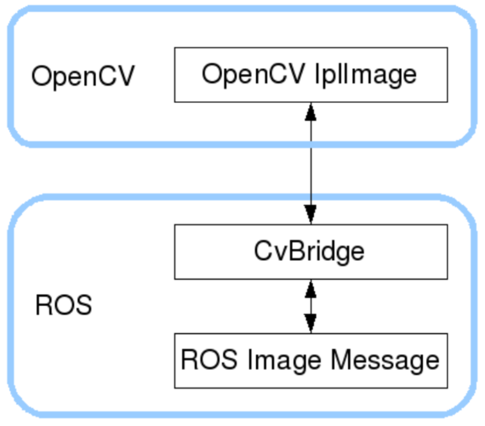
ROS はインストール時点で OpenCV(3.x 以降)をすでに組み込んでいますが、画像は RS 内で sensor msgs/Image メッセージ形式で伝送されるため、OpenCV で直接処理することはできません。このため、ROS は cv bridge を提供しています:
ROS Image ↔ OpenCV Mat(nompy array)間の効率的な変換は、ROS 画像処理の中心的な橋渡しです。
機能パッケージの依存関係設定
package.xml
コードファイル:7-2-2-8-ros-plus-opencv-fundamentals-package.xml
<?xml version="1.0"?>
<package format="2">
  <name>ros_opencv_demo</name>
  <version>0.0.1</version>
  <description>
    ROS + OpenCV sample package that uses cv_bridge to subscribe to USB camera images and process them with OpenCV.
  </description>

  <!-- maintainer information -->
  <maintainer email="you@example.com">your_name</maintainer>

  <!-- open-source license -->
  <license>BSD</license>

  <!-- build tool -->
  <buildtool_depend>catkin</buildtool_depend>

  <!-- ================= core dependencies ================= -->

  <!-- Python / ROS -->
  <depend>rospy</depend>

  <!-- ROS messages -->
  <depend>std_msgs</depend>
  <depend>sensor_msgs</depend>

  <!-- image-related dependencies -->
  <depend>cv_bridge</depend>
  <depend>image_transport</depend>

  <!-- Optional: enable this if you use PCL later. -->
  <!-- <depend>pcl_ros</depend> -->

  <!-- ================= optional exports ================= -->
  <export>
  </export>

</package>
CMakeLists.txt(Python ノードの最小構成)
コードファイル:7-2-2-8-ros-plus-opencv-fundamentals-example-02.cmake
cmake_minimum_required(VERSION 3.0.2)
project(ros_opencv_demo)
find_package(catkin REQUIRED COMPONENTS
  roscpp
  rospy
  std_msgs
  sensor_msgs
  cv_bridge
  image_transport
)
catkin_package()
include_directories(
  ${catkin_INCLUDE_DIRS}
)
USB カメラノードの起動
# Install dependencies if needed.
apt install -y ros-noetic-usb-cam
roslaunch usb_cam usb_cam-test.launch
カラー画像サブスクリプションノード(完全なコード)
ファイル名:usb_cam_image.py
コードファイル:7-2-2-8-ros-plus-opencv-fundamentals-usb_cam_image.py
#!/usr/bin/env python3

import rospy
import cv2
from sensor_msgs.msg import Image
from cv_bridge import CvBridge, CvBridgeError


class UsbCamImageNode:
    def __init__(self):
        rospy.init_node("usb_cam_image_node", anonymous=True)

        self.bridge = CvBridge()

        # subscribe to USB camera images
        self.image_sub = rospy.Subscriber(
            "/usb_cam/image_raw",
            Image,
            self.image_callback,
            queue_size=1
        )

        rospy.loginfo("USB Camera Image Subscriber Started")

    def image_callback(self, msg):
        try:
            # ROS Image → OpenCV BGR
            frame = self.bridge.imgmsg_to_cv2(msg, desired_encoding="bgr8")
        except CvBridgeError as e:
            rospy.logerr(e)
            return

        # display the image
        cv2.imshow("USB Camera Image", frame)
        cv2.waitKey(1)


if __name__ == "__main__":
    try:
        UsbCamImageNode()
        rospy.spin()
    except rospy.ROSInterruptException:
        pass
    finally:
        cv2.destroyAllWindows()
実行権限の付与
chmod +x usb_cam_image.py
cd /ros_ws
catkin_make
実行例
マルチターミナルツールのインストール
apt-get install terminator
# Run
terminator
ポップアップしたターミナル画面で ctrl + Shift + o ショートカットを使用して、別のターミナルを水平に開きます
ターミナル 1:カメラを起動する。
Roslaunch usb cam usb cam-test.launch
ターミナル 2:サブスクリプションノードを実行する
rosrun ros opencv demo usb_cam_image.py
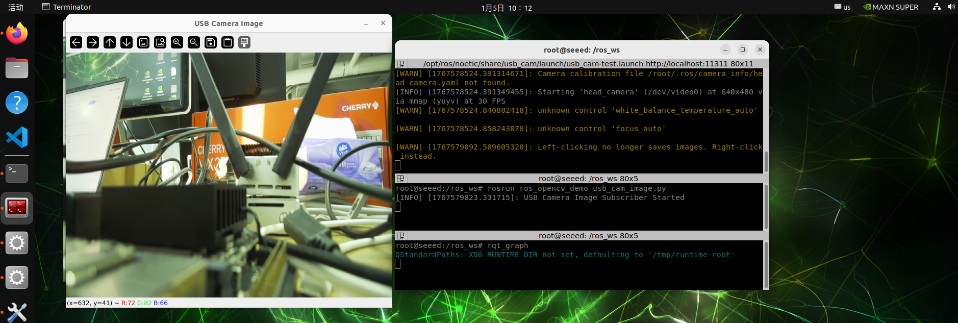
リアルタイムで USB カメラを表示する OpenCV ウィンドウが表示されます。
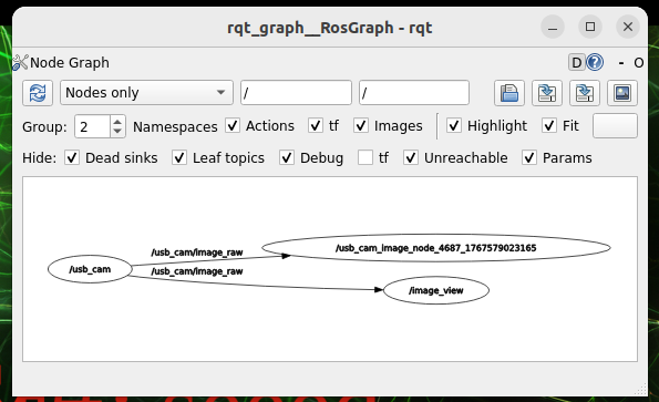
ノード通信の確認
別のターミナル操作を開始します:
rqt_graph図
7.2.2.9 MediaPipe 開発
MediaPipe の概要
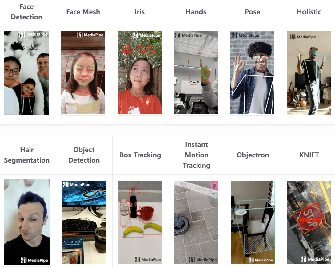
MediaPipe は、リアルタイムビジョンおよびマルチモーダル処理パイプラインを構築するために Google がオープンソースで公開している、高性能なクロスプラットフォームのセンサー計算フレームワークです。カメラ入力、モデル推論、後処理の各モジュールを効率的に連携させるグラフ計算(Graph)の仕組みにより、人体姿勢推定、手の認識、顔検出、キーポイントトラッキングといったタスクで広く利用されています。MediaPipe には、CPU でのリアルタイム推論をサポートする軽量な深層学習モデルが多数組み込まれており、Jetson やモバイルなどの組み込みプラットフォームとの親和性も高く、開発者は少量のコードで安定した低遅延のリアルタイム知覚アプリケーションを迅速に実現できます。
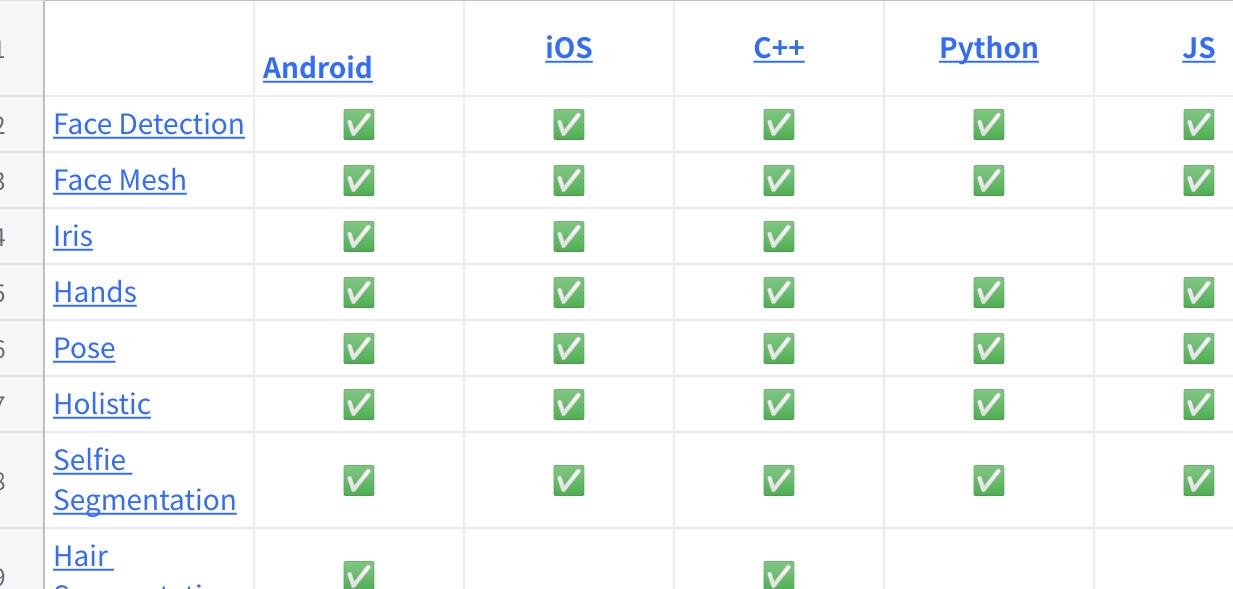
MediaPipe におけるディープラーニングソリューション
画像をクリックすると完全な表を確認できます
docker の起動
sudo docker run -it \
  --net=host \
  --privileged \
  -v /dev:/dev \
  -v /tmp/.X11-unix:/tmp/.X11-unix \
  -e DISPLAY=$DISPLAY \
  -e QT_X11_NO_MITSHM=1 \
  ros:noetic
使用例
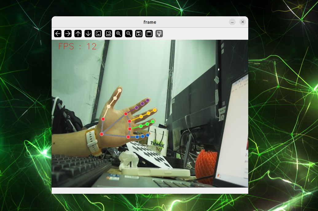
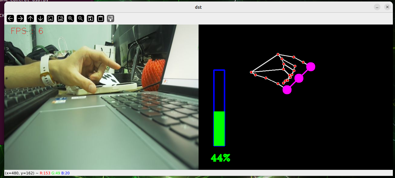
ハンドテスト
cd sources_code/ROS 1/mediapipe
python3 hand.py
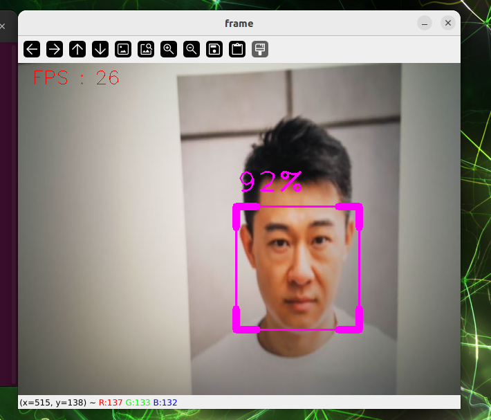
顔のチェック。
cd sources_code/ROS 1/mediapipe
python3 face_detection.py
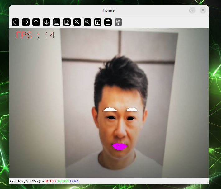
顔エフェクト。
cd sources_code/ROS 1/mediapipe
python3 face_effect.py
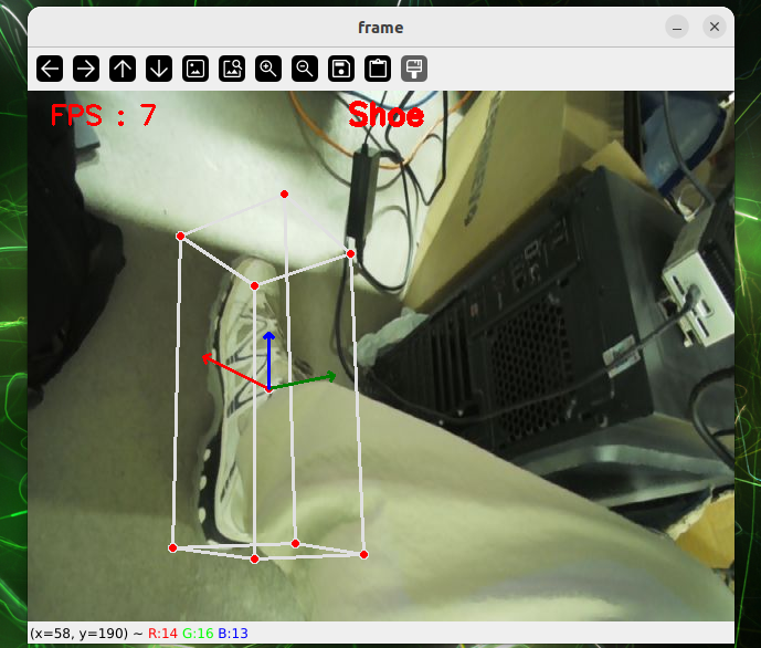
D 物体認識
cd sources_code/ROS 1/mediapipe
python3 object_reg.py
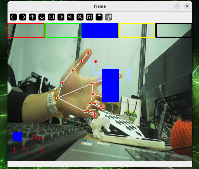
ブラシ
cd sources_code/ROS 1/mediapipe
python3 virtual_brush.py
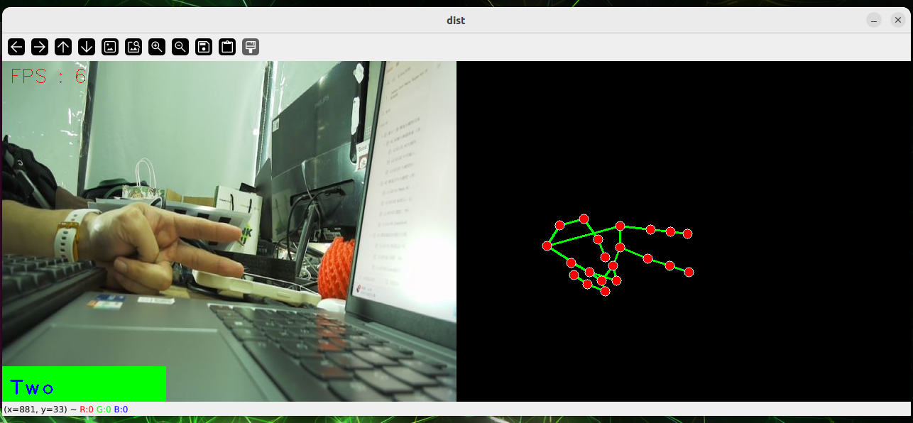
ジェスチャー認識。
cd sources_code/ROS 1/mediapipe
python3 gesture_recognition.py
指の制御。
cd sources_code/ROS 1/mediapipe
python3 hand_control.py
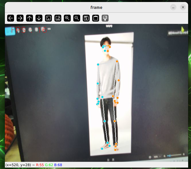
ポーズ推定
cd sources_code/ROS 1/mediapipe
python3 pose_estimation.py
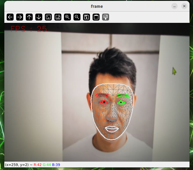
顔テスト
cd sources_code/ROS 1/mediapipe
python3 face_mesh.py
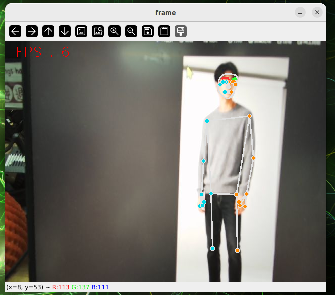
全体テスト
cd sources_code/ROS 1/mediapipe
python3 holistic.py
ケース分割
cd sources_code/ROS 1/mediapipe
python3 selfie_segmentation.py
図