Interface Description
FAN
The reComputer RK3576 exposes fan control through the Linux hwmon subsystem. Fan speed can be read in real time, and the PWM duty cycle can be set manually or left to the automatic thermal governor.
Hardware Monitor Paths
| Interface | Path | Description |
|---|---|---|
| Fan speed | /sys/class/hwmon/hwmon6/fan1_input | Current RPM |
| PWM value | /sys/class/hwmon/hwmon6/pwm1 | 0–255, controls duty cycle |
| PWM mode | /sys/class/hwmon/hwmon6/pwm1_enable | 0=off 1=manual 2=auto |
Thermal Zones
| Zone | Path |
|---|---|
| SoC | /sys/class/thermal/thermal_zone0/temp |
| Big Core | /sys/class/thermal/thermal_zone1/temp |
| Little Core | /sys/class/thermal/thermal_zone2/temp |
| DDR | /sys/class/thermal/thermal_zone3/temp |
| NPU | /sys/class/thermal/thermal_zone4/temp |
| GPU | /sys/class/thermal/thermal_zone5/temp |
Temperature values are in millidegrees Celsius — divide by 1000 to get °C.
Reading Fan Speed
cat /sys/class/hwmon/hwmon6/fan1_inputOutput is in RPM. Example: 2161
Read all temperatures at once:
for zone in /sys/class/thermal/thermal_zone*; do
    name=$(cat $zone/type)
    temp=$(( $(cat $zone/temp) / 1000 ))
    echo "$name: ${temp}°C"
done
Controlling Fan Speed
- Switch to manual mode:
echo 1 | sudo tee /sys/class/hwmon/hwmon6/pwm1_enable- Set PWM value (0–255):
| PWM Value | Approximate Speed |
|---|---|
| 0 | Fan off |
| 64 | ~25% |
| 128 | ~50% |
| 192 | ~75% |
| 255 | Full speed |
# Set to 50%
echo 128 | sudo tee /sys/class/hwmon/hwmon6/pwm1- Restore automatic thermal control:
echo 2 | sudo tee /sys/class/hwmon/hwmon6/pwm1_enableAuto Thermal Control Script
This script adjusts fan speed based on SoC temperature and runs continuously in the background.
#!/bin/bash
TEMP_SENSOR="/sys/class/thermal/thermal_zone0/temp"
PWM_ENABLE="/sys/class/hwmon/hwmon6/pwm1_enable"
PWM_VALUE="/sys/class/hwmon/hwmon6/pwm1"

echo 1 > $PWM_ENABLE

while true; do
    TEMP=$(( $(cat $TEMP_SENSOR) / 1000 ))

    if   [ $TEMP -lt 40 ]; then PWM=50
    elif [ $TEMP -lt 50 ]; then PWM=100
    elif [ $TEMP -lt 60 ]; then PWM=160
    elif [ $TEMP -lt 70 ]; then PWM=210
    else                        PWM=255
    fi

    echo $PWM > $PWM_VALUE
    echo "$(date '+%H:%M:%S') Temp: ${TEMP}°C  PWM: $PWM"
    sleep 5
done
Save as fan-control.sh and run:
chmod +x fan-control.sh
sudo ./fan-control.sh
Run in the background:
sudo nohup ./fan-control.sh > /var/log/fan-control.log 2>&1 &systemd Service
- Copy the script:
sudo cp fan-control.sh /usr/local/bin/fan-control.sh
sudo chmod +x /usr/local/bin/fan-control.sh- Create the service file:
sudo tee /etc/systemd/system/fan-control.service << 'EOF'
[Unit]
Description=Fan Speed Controller
After=multi-user.target

[Service]
Type=simple
ExecStart=/usr/local/bin/fan-control.sh
Restart=on-failure
RestartSec=5

[Install]
WantedBy=multi-user.target
EOF- Enable and start:
sudo systemctl daemon-reload
sudo systemctl enable fan-control
sudo systemctl start fan-control
sudo systemctl status fan-control
Quick Reference
# Read fan RPM
cat /sys/class/hwmon/hwmon6/fan1_input

# Read SoC temperature
echo "$(( $(cat /sys/class/thermal/thermal_zone0/temp) / 1000 ))°C"

# Full speed
echo 1 | sudo tee /sys/class/hwmon/hwmon6/pwm1_enable
echo 255 | sudo tee /sys/class/hwmon/hwmon6/pwm1

# Low speed
echo 1 | sudo tee /sys/class/hwmon/hwmon6/pwm1_enable
echo 64 | sudo tee /sys/class/hwmon/hwmon6/pwm1

# Restore auto
echo 2 | sudo tee /sys/class/hwmon/hwmon6/pwm1_enable
Tested Environment
| Item | Value |
|---|---|
| Device | reComputer RK3576 DevKit |
| OS | Linux 6.1 (Debian-based) |
| hwmon interface | /sys/class/hwmon/hwmon6 (pwmfan) |
| Idle fan speed | ~2155 RPM |
| Idle SoC temp | ~36°C |
LED Indicator Status
This device features three on-board LED indicators (Power, Status, and User) on the front panel. These LEDs allow users to monitor the hardware power-on sequence, observe system runtime behavior, and utilize a fully programmable interface for custom software interactions.

-
LED States & Default Hardware Behavior Under the default system firmware, the LEDs exhibit the following standard behaviors during boot-up and post-boot operations:
-
Developer Essential: Control Boundaries Before starting secondary development, it is critical to understand the underlying hardware routing of each LED to avoid unnecessary troubleshooting:
-
❌ Power LED (Red): Pure Hardware Control. This LED is hardwired directly to the main power rail. There is no GPIO or kernel interface connected to it. It cannot be controlled via software or commands.
-
❌ Status LED (Green): System-level Hardware Control. This LED is physically managed by the underlying hardware power management logic or PMIC firmware to reflect core system stability. It does not expose any interface to the Linux user space and cannot be controlled via software or commands.
-
User LED (RGB Tri-color): Fully Developer Controllable! This is an RGB LED capsule wired to the on-board GPIO expander (
gpiochip6). It is the only indicator on the device open for custom programming and software automation. By default, the system claims the blue channel (USER_LED_B) as a heartbeat indicator, leaving the red and green channels idle. -
User RGB LED Control Guide In the Linux environment (e.g., Armbian), it is recommended to use the modern
gpiodtoolchain (gpioinfo/gpioset) to manipulate the idle Red and Green channels, and the standard Linuxsysfsinterface to control the Blue channel. Locate the LED In the system, LEDs are managed via thesysfsinterface. Run the following command to verify the LED node:
ls /sys/class/leds/user-ledExpected Output :

Manual Control (ON/OFF)
Before controlling the LED manually, you need to set its trigger mode to none.
echo none | sudo tee /sys/class/leds/user-led/triggerTurn ON/OFF the LED
# Turn ON
echo 1 | sudo tee /sys/class/leds/user-led/brightness
# Turn OFF
echo 0 | sudo tee /sys/class/leds/user-led/brightness
Automated Trigger Modes The kernel provides various triggers to automate LED behavior based on system events.
# Heartbeat Mode
echo heartbeat | sudo tee /sys/class/leds/user-led/trigger
# Custom Timer Mode (Blinking)
# Enable timer
echo timer | sudo tee /sys/class/leds/user-led/trigger
# Set intervals
echo 500 | sudo tee /sys/class/leds/user-led/delay_on
echo 500 | sudo tee /sys/class/leds/user-led/delay_off
Persistent Configuration on Boot
Since changes in /sys are volatile and reset after reboot, you can make them permanent by adding a cron job or using rc.local.
Button
The reComputer RK3576 series motherboards are equipped with 3 onboard physical buttons, primarily used for power control and low-level firmware flashing.
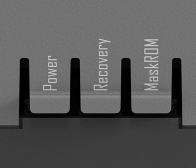
Note: When using Recovery or MaskROM for flashing, ensure the device's Type-C OTG port is connected to the host PC via a data cable. You will need to use official Rockchip tools (such as RKDevTool for Windows or upgrade_tool for Linux) to execute the operations.
GPIO
The motherboard provides a standard 40-pin expansion header at the top, offering developers a comprehensive set of low-level hardware interfaces. These include power, debugging, and common industrial communication buses (I2C, UART, SPI, CAN, etc.), making it easy to connect external sensors, driver boards, or perform system-level debugging.
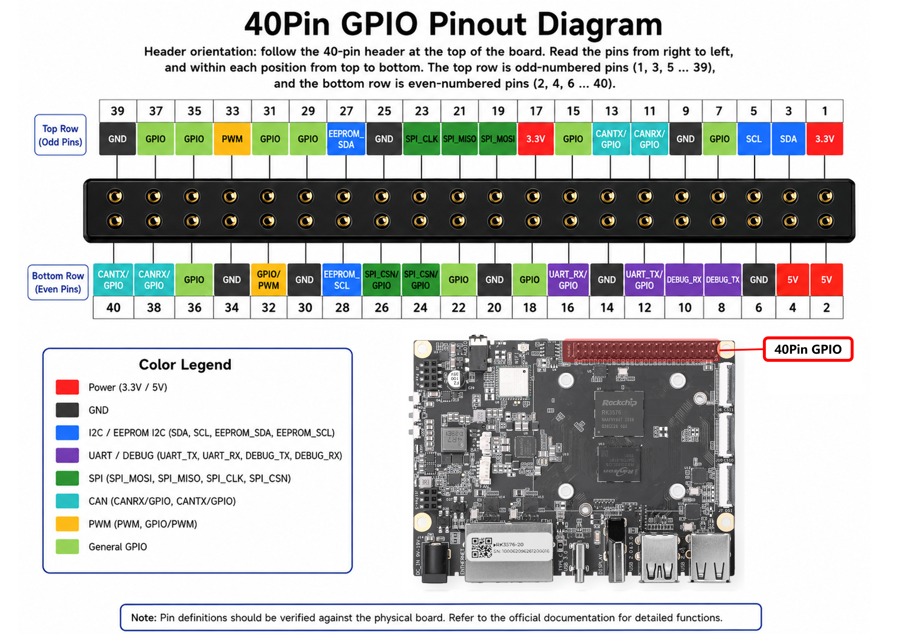
40-Pin Pinout Table
GPIO Usage
By default, most pins on the 40-Pin header function as standard GPIOs, unless pre-allocated by system drivers. The standard gpiod toolset (gpiodetect, gpioinfo, gpioset, gpioget) is recommended for shell-level manipulation.
To manipulate Physical Pin 21 (which is specified as a General GPIO and currently free):
- Locate its mapped controller and line number:
sudo gpioinfo | grep -i PIN_21Output:
line 14: "PIN_21" unused input active-highThis indicates it belongs to gpiochip1, Line 14.
- Set the pin to High (e.g., Turn on an LED):
gpioset gpiochip1 14=1- Set the pin to low:
gpioset gpiochip1 14=0- Read the input status of Physical Pin 27: Querying
sudo gpioinfo | grep -i PIN_27shows it maps togpiochip4, Line23:
gpioget gpiochip4 23To unlock the specialized peripheral hardware (I2C, UART, CAN, PWM) labeled on the pinout, you must explicitly enable its corresponding Device Tree Overlay (DTBO). Otherwise, they will continue to function merely as generic GPIOs.
All 40-Pin specific overlay configurations reside in /boot/dtb/rockchip/overlay/ and follow the strict naming prefix recomputer-rk3576-devkit-40pin-:
Configuration Procedure:
- Open the system environment configuration file:
sudo nano /boot/armbianEnv.txt- Locate the
overlays=line (or append it to the end of the file if missing), then insert the desired overlay name without the.dtboextension. Separate multiple overlays with a space:
overlays=recomputer-rk3576-devkit-40pin-i2c3 recomputer-rk3576-devkit-40pin-can0- Save and exit (
Ctrl+O, Enter,Ctrl+X), then restart the hardware to apply the device tree modification:
sudo rebootNote: SPI Active by Default
The SPI Bus pins (Pins 19, 21, 23, 24, 26) are enabled by default at boot time. You do NOT need to assign any custom DTBO for SPI in
armbianEnv.txt.Hardware Architecture Sharing: The physical SPI signals on the 40-Pin header share the exact same hardware bus domain with the onboard 4G LTE / LoRaWAN / Hailo Wi-Fi expansion slots. To facilitate an out-of-the-box experience for these communication modules, the base operating system keeps this SPI channel permanently active.
Developer Recommendation: If you connect custom third-party SPI breakout boards onto the 40-Pin expansion header, ensure you handle Chip Select (CS) and addressing carefully to circumvent communication bus deadlocks with the built-in modules.
USB
This device provides multiple physical USB interfaces mapped to the reComputer RK3576 series. These interfaces handle external peripheral attachment, system firmware flashing (OTG), and secondary display output.
The USB resource allocation is defined as follows:
| Interface Location / Label | Physical Form Factor | Bus Protocol & Maximum Bandwidth | Hardware Specification & Controller Routing |
|---|---|---|---|
| USB 3.0 Host | USB Type-A | USB 3.2 Gen 1x1 (5 Gbps) | Routed via the internal USB 3.0 Controller. Provides high-bandwidth data channels optimized for USB 3.0 Industrial Cameras, NVMe storage expansion, or high-speed DAQ modules. |
| USB 2.0 Host | USB Type-A (Multiple) | USB 2.0 (480 Mbps) | Managed by the USB 2.0 Host Controller. Used for standard peripherals such as keyboards, mice, 4G/5G cellular modems, hardware encryption dongles, or USB-to-UART bridge boards. |
| USB Type-C | USB Type-C | USB 3.0 / 2.0 OTG + DP 1.4 Alt Mode | A multi-protocol composite port routed to the RK3576 USB 3.0 OTG controller and the DisplayPort (DP) TX PHY. Supports bidirectional host/device roles and hardware video streaming. |
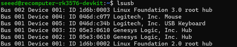
Using lsusb allows you to view information about the USB devices connected to the system:
Note: USB Type-C Interface Architecture
A. System Flashing & Maintenance (USB OTG Device Mode): Triggered via Recovery / MaskROM keys, the port boots into device mode for low-level firmware flashing using RKDevTool.
B. DisplayPort Output (DP 1.4 Alt Mode): Multiplexes hardware video lanes to drive a monitor directly via Type-C cables or adapters, delivering standard DP 1.4 displays.
C. Standard Native Host Mode: Defaults to a standard USB 3.0 Host during normal OS runtime to interface directly with Type-C storage, network adapters, or hubs.
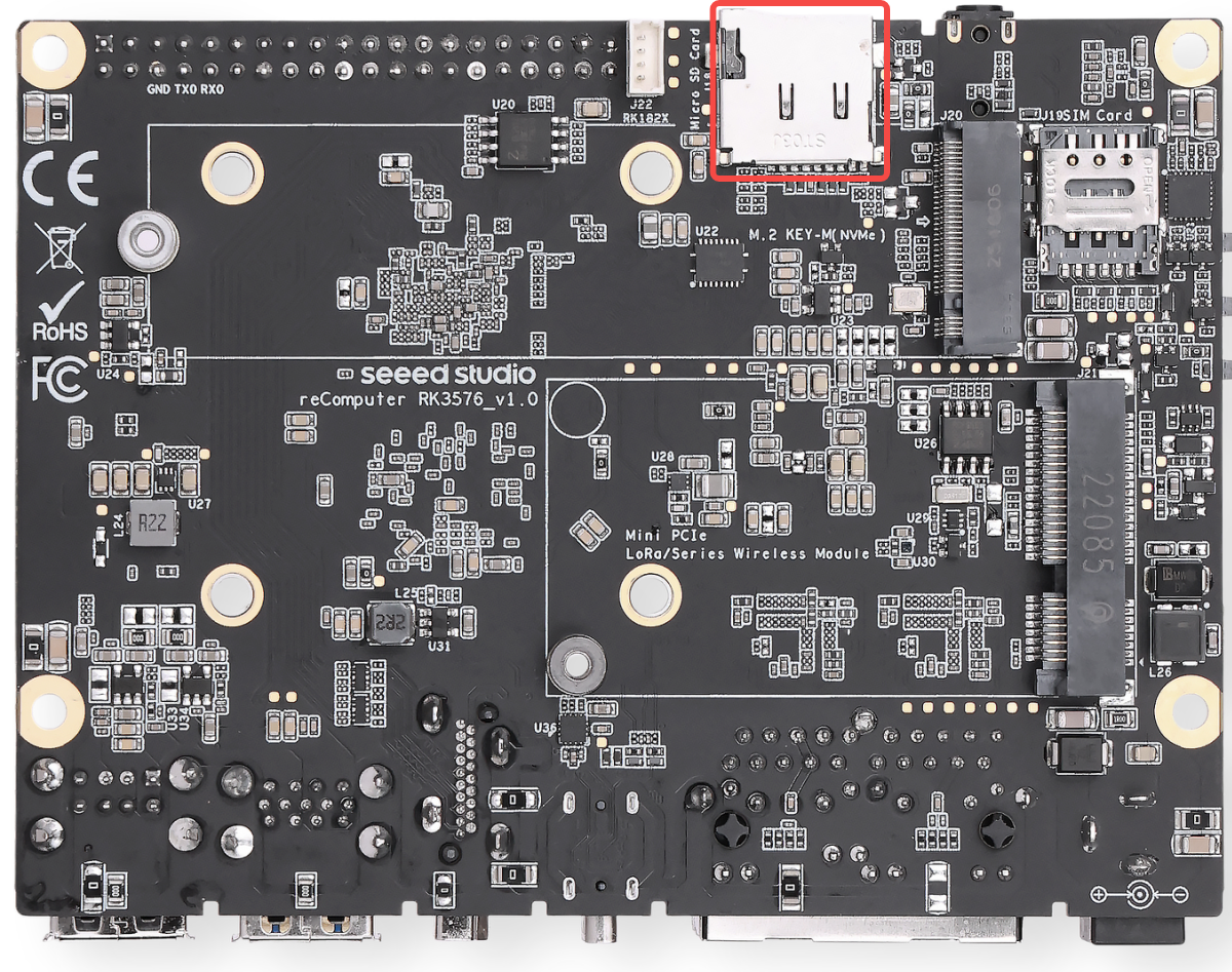
SD Card Slot
The motherboard is equipped with one standard Micro SD (TF) card slot, routed directly to the SDMMC0 bus of the RK3576 SOC. This interface is primarily utilized for system booting, running the operating system (such as Armbian OS), and local data storage.
Out-of-the-Box Experience The device comes standard with an included 32GB Class 10 Micro SD card. This card has passed rigorous compatibility testing by Seeed Studio and is perfectly capable of handling daily Armbian OS operations, basic network configurations, and lightweight edge AI algorithm validations, allowing developers to get started immediately.
Note: Boot Priority & Storage Guidance
Boot Priority Mechanism (MaskROM Stage): The firmware boot sequence on the RK3576 is strictly controlled by the low-level MaskROM. If bootable firmware coexists on both the Micro SD card and the onboard eMMC, the MaskROM will prioritize loading the SPL (Secondary Program Loader) from the Micro SD card. Please pay close attention to this physical characteristic during firmware upgrades or multi-OS switching.
NVMe Boot Limitation (U-Boot Stage): M.2 NVMe SSDs are NOT within the direct MaskROM boot path. The system cannot perform the initial stage-1 boot directly from a raw NVMe drive. To run the OS from an NVMe SSD, the system must first execute the bootloader on either the Micro SD card or the eMMC to enter the U-Boot stage, where U-Boot will then initialize, load, and hand over control to the main OS residing on the NVMe storage.
Heavy Workload Upgrade Recommendations: If you plan to deploy applications with high-frequency I/O read/write demands at the edge (such as running large databases with continuous local logging, or managing complex Docker container clusters), the massive volume of 4K random read/writes may hit the performance bottleneck of a standard Class 10 card. For such heavy-duty industrial scenarios, we recommend migrating the core OS rootfs to an M.2 NVMe SSD (via U-Boot chain-loading), or upgrading to a high-performance Micro SD card explicitly rated for A1 or A2 (Application Performance Class) to ensure optimal system responsiveness.
Mount Point: In Armbian OS, the Micro SD card is typically enumerated as
/dev/mmcblk0.
SIM Card Slot
The motherboard features one onboard card slot, explicitly designed to work with 4G LTE cellular modules installed in the Mini-PCIe slot. By inserting a standard carrier SIM card, the device can achieve edge-to-cloud cellular connectivity in environments without wired Ethernet.
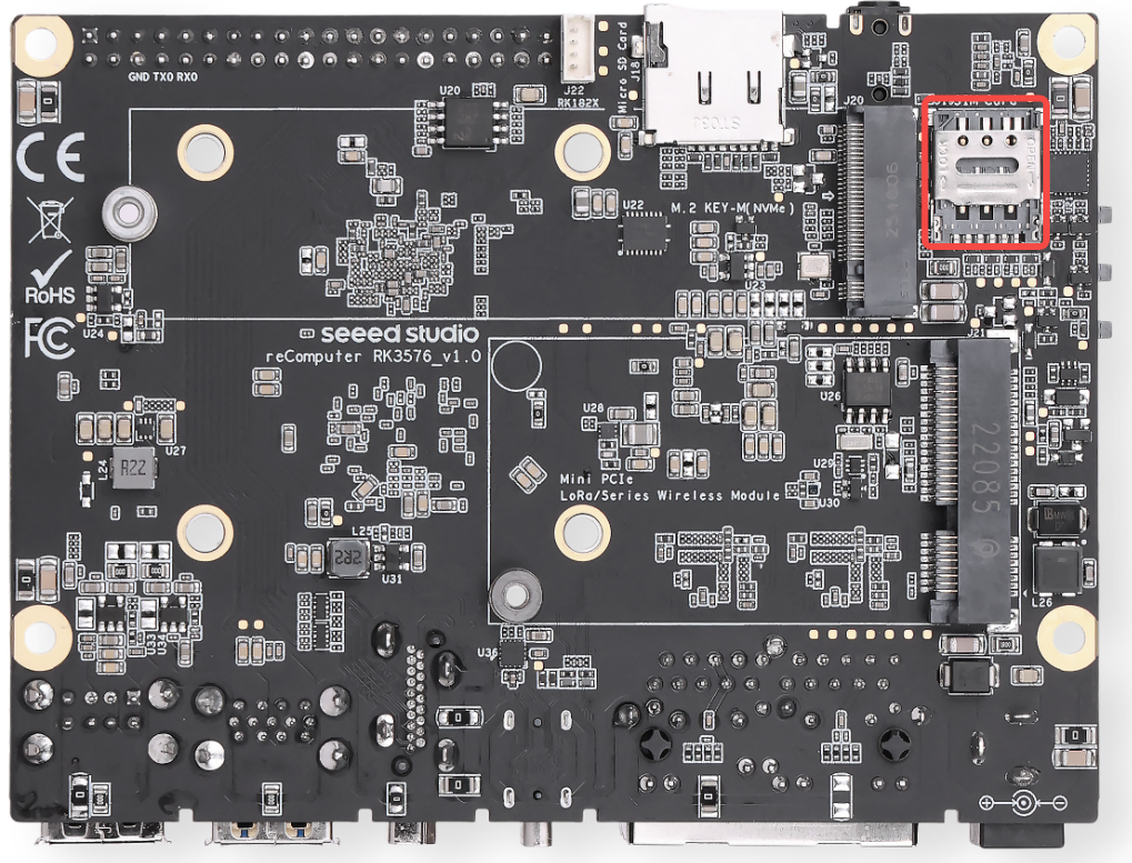
Hardware Architecture & Mechanism The signal lines of the Nano SIM slot are routed directly to the specific pins (such as UIM_PWR, UIM_DATA, UIM_CLK, UIM_RESET) of the Mini-PCIe slot.
- Non-SOC Direct Connection: Note that the SIM card signals do not interface directly with the RK3576 SOC. Instead, they are fully managed and driven by the 4G module installed in the Mini-PCIe slot. Consequently, the SIM card will only function when a compatible 4G module is active.
Note: Developer Notes & Operating Standards
Strictly No Hot-Plugging: Always insert or remove the SIM card while the device is completely powered off (DC power or PoE disconnected). Hot-plugging the SIM card while the system is live can permanently damage the SIM interface on the 4G module or cause network-related system crashes.
Form Factor Specifications: This slot strictly supports Nano SIM cards (4FF), which is the smallest standard size used in modern smartphones. Avoid using Micro or Standard SIM cards with cheap plastic adapters, as they can easily get stuck or bend the internal pins of the slot.
Insertion Orientation: Please check the silk-screen icon or structural notch near the slot before insertion. Typically, the SIM card should be inserted with the gold contacts facing down and the notched corner going in first (please follow the physical alignment marking on the board).
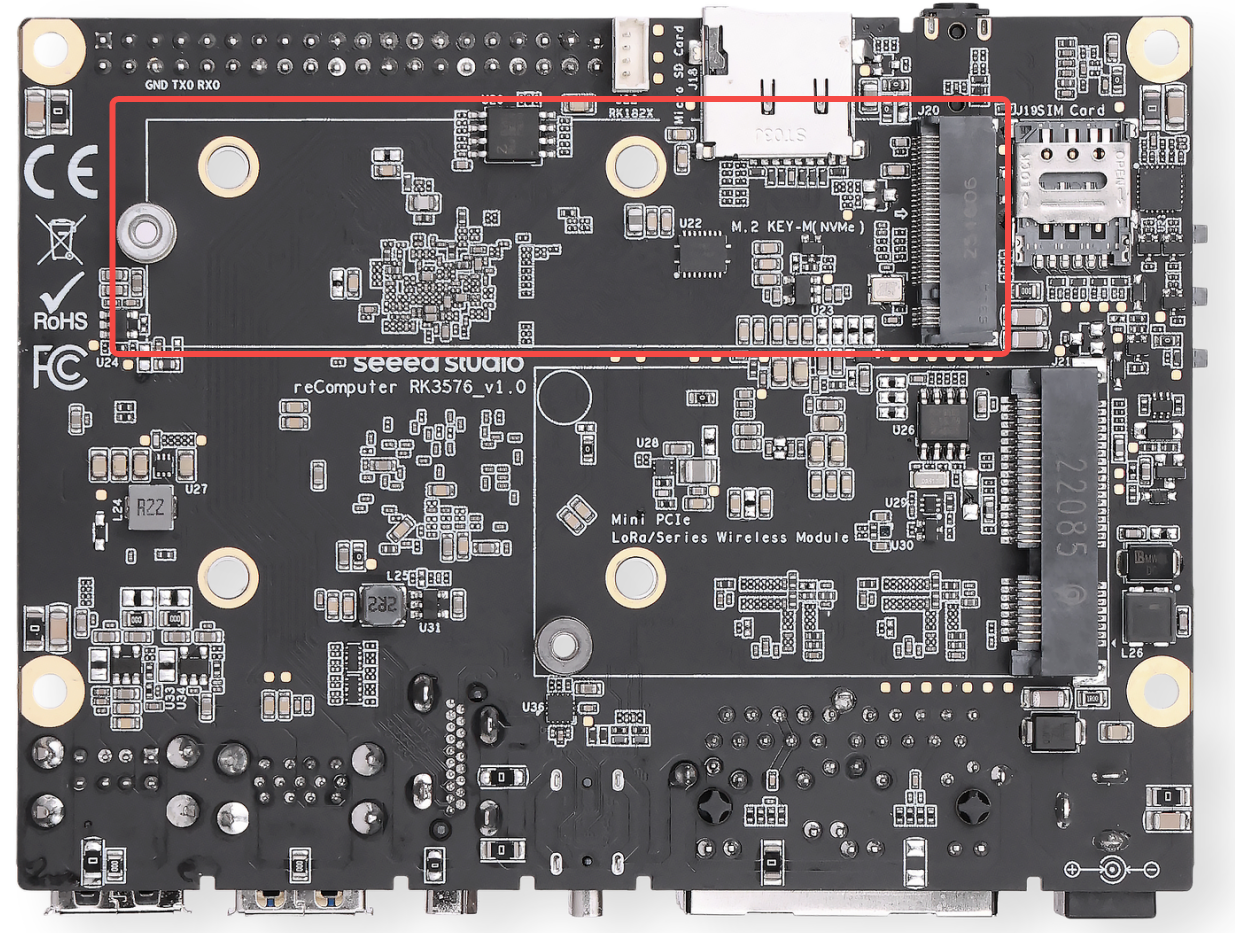
M.2 Key M 2280 Slot
The motherboard is equipped with one standard M.2 Key M 2280 slot, driven by a PCIe 2.1 x1 bus. It is designed for high-speed storage expansion or edge AI computing acceleration.
Supported Devices
- NVMe SSD: Supports standard 2280 NVMe Solid State Drives for system booting, high-capacity data storage, or housing large AI models.
- AI Accelerator: Compatible with M.2 Key M based AI accelerator modules to enhance edge inference capabilities.
Tested & Verified Devices To ensure optimal compatibility and system stability, we highly recommend using the M.2 extension modules that have been fully tested and verified by Seeed Studio:
- Storage
- Official Seeed Studio 2280 NVMe SSDs: https://www.seeedstudio.com/M-2-2280-SSD-128GB-p-5332.html
- AI Accelerators
- Rockchip Series: RK1820 / RK1828
- Hailo Series: Hailo-8
- DeepX Series: DX-M1
Note:
Protocol Compatibility: This slot strictly supports PCIe NVMe devices. M.2 SATA SSDs are NOT supported and will not be recognized by the OS.
Bandwidth Limitation: The slot operates on a PCIe 2.1 x1 lane, providing a theoretical maximum bandwidth of approximately 500 MB/s. When purchasing an NVMe SSD, standard cost-effective Gen3/Gen4 drives are sufficient; ultra-high-speed Gen4 SSDs will be bottlenecked by the PCIe 2.1 x1 interface.
Form Factor: The mounting standoff is designed specifically for 2280 (22mm x 80mm) modules.
SSD Use Guide
lsblk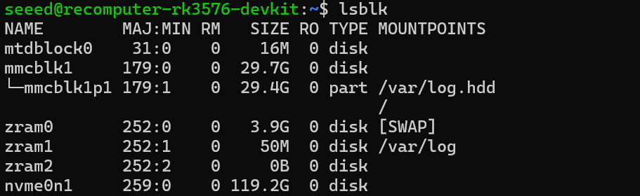
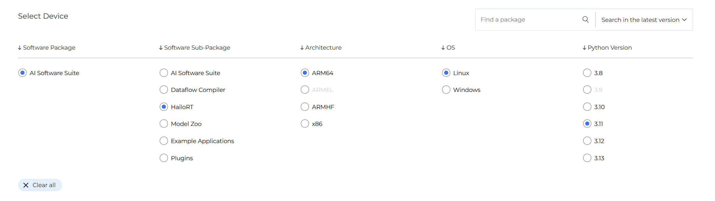
Hailo YOLOv11 Deployment & Inference Guide
Package Installation After installing the base PCIe driver, a system reboot is required for changes to take effect.
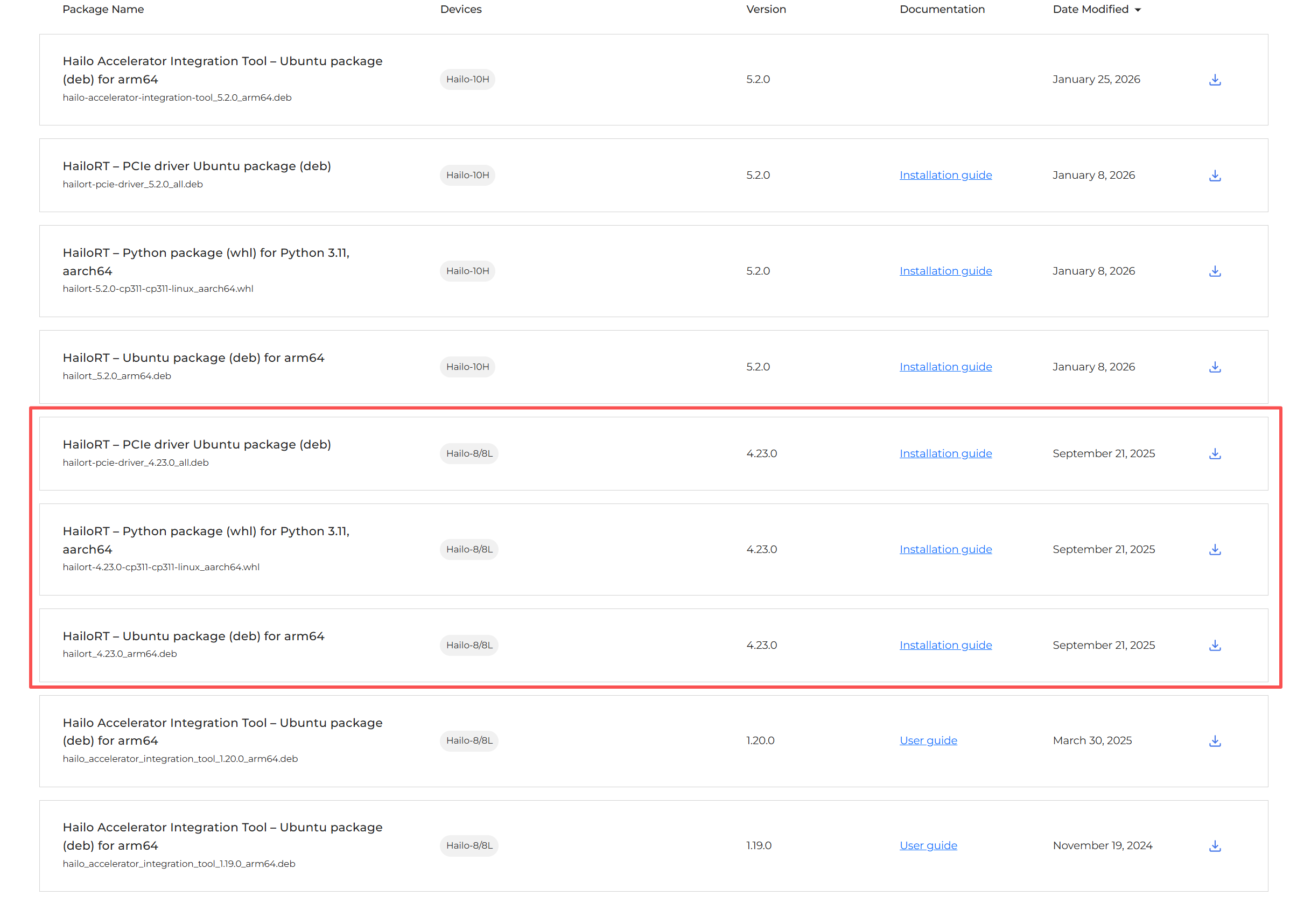
# Install the PCIe driver
sudo dpkg -i hailort-pcie-driver_4.23.0_all.deb
# Reboot the system
sudo reboot
# After reboot, verify the driver is loaded
lsmod | grep hailo
# Install HailoRT
sudo dpkg -i hailort_4.23.0_arm64.deb
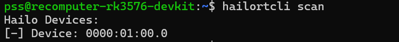
# Scan and verify device status
hailortcli scan
# Create and activate a virtual environment
python3 -m venv hailo_env
source hailo_env/bin/activate
# Install HailoRT Python library
pip install hailort-4.23.0-cp311-cp311-linux_aarch64.whl
# Verify installation and device connection
python3 -c "from hailo_platform import VDevice; vdev = VDevice(); print('Successfully connected via VDevice! Device info:', vdev)"

Install Hailo Model Zoo To run official pre-trained models, you need to install the Hailo Model Zoo and its system dependencies.
# 1. Install required system libraries
sudo apt update
sudo apt install -y git libglib2.0-0 libgl1-mesa-glx

# 2. Clone the official repository (latest branch recommended)
git clone https://github.com/hailo-ai/hailo_model_zoo.git
cd hailo_model_zoo
pip install -e .
Running the YOLOv11 Model
- Check camera devices: Identify your webcam mount point.
v4l2-ctl --list-devices- Download model: Ensure the
yolov11n.hefmodel file is downloaded and placed in your working directory.
Create a file named webcam_yolo11.py and paste the code below. Adjust the HEF_PATH and DEVICE_ID under the configuration section to match your setup.
import numpy as np
import cv2
import time
from hailo_platform import (VDevice, HEF, InferVStreams, ConfigureParams,
                            HailoStreamInterface, InputVStreamParams, OutputVStreamParams)

# ================= Configuration =================
HEF_PATH = 'yolov11n.hef'
DEVICE_ID = "/dev/video40"  # Update based on v4l2-ctl output
CONF_THRESHOLD = 0.45

# COCO Dataset 80 Class Labels
COCO_CLASSES = [
    "person", "bicycle", "car", "motorcycle", "airplane", "bus", "train", "truck", "boat", "traffic light",
    "fire hydrant", "stop sign", "parking meter", "bench", "bird", "cat", "dog", "horse", "sheep", "cow",
    "elephant", "bear", "zebra", "giraffe", "backpack", "umbrella", "handbag", "tie", "suitcase", "frisbee",
    "skis", "snowboard", "sports ball", "kite", "baseball bat", "baseball glove", "skateboard", "surfboard",
    "tennis racket", "bottle", "wine glass", "cup", "fork", "knife", "spoon", "bowl", "banana", "apple",
    "sandwich", "orange", "broccoli", "carrot", "hot dog", "pizza", "donut", "cake", "chair", "couch",
    "potted plant", "bed", "dining table", "toilet", "tv", "laptop", "mouse", "remote", "keyboard", "cell phone",
    "microwave", "oven", "toaster", "sink", "refrigerator", "book", "clock", "vase", "scissors", "teddy bear",
    "hair drier", "toothbrush"
]
# ==================================================

def main():
    # 1. Initialize Hailo Hardware
    hef = HEF(HEF_PATH)
    input_vstream_info = hef.get_input_vstream_infos()[0]
    input_h, input_w = input_vstream_info.shape[:2]

    cap = cv2.VideoCapture(DEVICE_ID)
    if not cap.isOpened():
        print("Cannot open webcam")
        return

    # Setup inference variables
    prev_time = 0

    with VDevice() as target:
        config_params_dict = ConfigureParams.create_from_hef(hef, HailoStreamInterface.PCIe)
        network_group = target.configure(hef, config_params_dict)[0]
        with network_group.activate():
            vstream_params = (InputVStreamParams.make_from_network_group(network_group),
                              OutputVStreamParams.make_from_network_group(network_group))
            with InferVStreams(network_group, vstream_params[0], vstream_params[1]) as vstreams:
                print("[INFO] Initialization successful! Running YOLOv11 real-time detection...")
                while True:
                    start_time = time.time()  # Record start time for FPS
                    ret, frame = cap.read()
                    if not ret:
                        break

                    # Preprocessing (Convert to RGB based on previous validation)
                    frame_rgb = cv2.cvtColor(frame, cv2.COLOR_BGR2RGB)
                    resized = cv2.resize(frame_rgb, (input_w, input_h))
                    input_tensor = np.expand_dims(resized, axis=0)

                    # Inference
                    outputs = vstreams.infer(input_tensor)

                    # Parsing and Drawing
                    h, w, _ = frame.shape
                    for name, class_list in outputs.items():
                        # Iterate through 80 classes
                        for class_id, detections in enumerate(class_list[0]):
                            if len(detections) > 0:
                                for det in detections:
                                    if len(det) >= 5:
                                        ymin, xmin, ymax, xmax, confidence = det[:5]
                                        if confidence > CONF_THRESHOLD:
                                            # Coordinate Mapping
                                            left, top = int(xmin * w), int(ymin * h)
                                            right, bottom = int(xmax * w), int(ymax * h)

                                            # Get class name, display ID if out of bounds
                                            class_name = COCO_CLASSES[class_id] if class_id < len(COCO_CLASSES) else f"ID {class_id}"

                                            # Draw bounding box
                                            cv2.rectangle(frame, (left, top), (right, bottom), (0, 255, 0), 2)
                                            # Draw background and label text
                                            label = f"{class_name}: {confidence:.2f}"
                                            cv2.putText(frame, label, (left, top - 10),
                                                        cv2.FONT_HERSHEY_SIMPLEX, 0.5, (0, 255, 0), 2)

                    # Calculate and display real-time FPS
                    curr_time = time.time()
                    fps = 1 / (curr_time - start_time)
                    # Print in the top left corner
                    cv2.putText(frame, f"FPS: {fps:.1f}", (20, 40),
                                cv2.FONT_HERSHEY_SIMPLEX, 1, (0, 0, 255), 2)

                    # Display window
                    cv2.imshow('reComputer RK3576 - Hailo YOLOv11', frame)
                    if cv2.waitKey(1) & 0xFF == ord('q'):
                        break

    cap.release()
    cv2.destroyAllWindows()

if __name__ == "__main__":
    main()
RK182x Deployment & Inference Guide
RK182x supports the coprocessor mode, where the host SoC (e.g., RK3588/RK3576) acts as the system core, responsible for task scheduling, resource allocation, and overall control. It connects to the RK1820/RK1828 acceleration unit via high-speed PCIe (typically trained to Gen2 x1 at 5 GT/s, providing ~400 MB/s unidirectional bandwidth) or USB 3.0 interfaces. Both RK1820 and RK1828 share the same PCI Device ID (1d87:182a). The development framework consists of the PC-side model conversion tool (RKNN3 Toolkit) and the board-side runtime environment (RKNN3 Runtime).
Option A: Rapid Automated Deployment (Recommended) Using the precompiled automated installer package from the SDK allows for a one-click deployment of the kernel driver, device firmware, runtime libraries, debugging tools, and system auto-start services.
# Push the package via ADB from PC to Board
# Optional packages include:
#   - rknn3_rk182x_m2_installer_arm64.tgz (M.2 Module)
adb push rknn3_rk182x_m2_installer_arm64.tgz /tmp/installer.tgz
adb shell "cd /tmp && tar xzf installer.tgz && ./install.sh"

# Note: A hard power cycle (physical power off) is MANDATORY to ensure proper hardware and firmware loading.
sudo poweroff
If manual control over driver binding is required during development and debugging, or when operating in an environment without the automated package installed, execute the following system bus commands in order. Note: RK1820 requires explicit manual activation of BusMaster after driver probing.
# Force driver override and trigger binding
echo pcie-rkep | sudo tee /sys/bus/pci/devices/0000:01:00.0/driver_override
echo 0000:01:00.0 | sudo tee /sys/bus/pci/drivers/pcie-rkep/bind

# Enable the BusMaster register to activate accelerator card bus mastering
sudo setpci -s 01:00.0 COMMAND=0x0406
The host system runs Python 3.11 by default. Before deployment, ensure you have converted your models on an x86 machine using the RKNN3 Toolkit into the dedicated .rknn format (for both LLMs and CNNs) and uploaded the resulting files (e.g., qwen2_5_1_5b_rk1820.rknn) to the host.
# 1. Create workspace
mkdir -p ~/rk_182x_work && cd ~/rk_182x_work

# 2. Clone Model Zoo and Toolkit repositories
git clone --recursive https://github.com/airockchip/rknn3-model-zoo.git
git clone https://github.com/airockchip/rknn3-toolkit.git

# 3. Install rknn3-toolkit-lite
cd rknn3-toolkit/rknn3-toolkit-lite/packages
pip3 install ./rknn3_toolkit_lite-1.0.0-cp311-cp311-linux_aarch64.whl

# 4. Install dependencies
pip3 install -r requirements.txt
Mini-PCIe Slot
The motherboard features one standard Mini-PCIe (Mini PCI Express) slot, primarily designed for expanding industrial-grade wireless communication modules such as 4G LTE, LoRaWAN, or Wi-Fi HaLow.
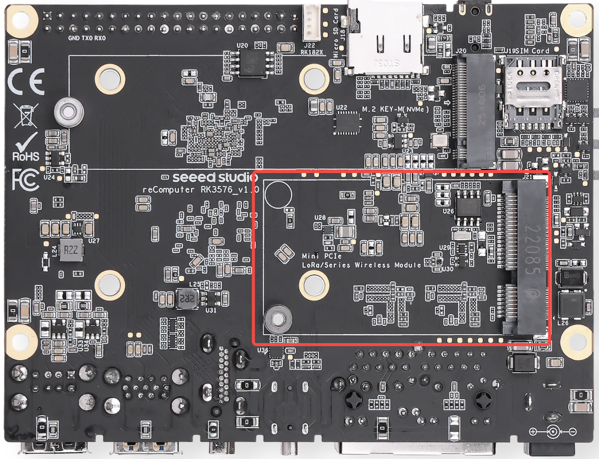
Signal & Bus Architecture This Mini-PCIe slot routes both PCIe and USB signals internally, ensuring excellent compatibility with the vast majority of mainstream wireless communication modules on the market.
- Cellular Expansion: In conjunction with the onboard Nano SIM card slot, it allows direct insertion of 4G LTE modules to enable cellular network connectivity.
Tested & Verified Devices To ensure optimal compatibility and system stability, we highly recommend using the Mini-PCIe modules that have been fully tested and verified by Seeed Studio:
- 4G Cellular Network
- Official recommended 4G LTE Mini-PCIe module
- LoRaWAN & IoT Wireless
- USB-based / SPI-based LoRaWAN gateway modules
- Wi-Fi HaLow (802.11ah) long-range, low-power wireless modules
Note:
SIM Card Integration: When using a 4G LTE module, please insert the Nano SIM card into the onboard slot while the device is powered off. Hot-plugging the SIM card may cause module recognition failure or permanent damage.
Antenna Routing: Since industrial enclosures can shield wireless signals, always connect IPEX-to-SMA pigtails to route the antennas outside the chassis when deploying 4G or LoRaWAN modules.
Driver & Network Configuration: Most industrial 4G modules require specific USB serial drivers (such as the
optiondriver) in Armbian OS. Developers can use NetworkManager orpppdto establish cellular connections.
4G Module (EC25) Configuration & Testing Guide
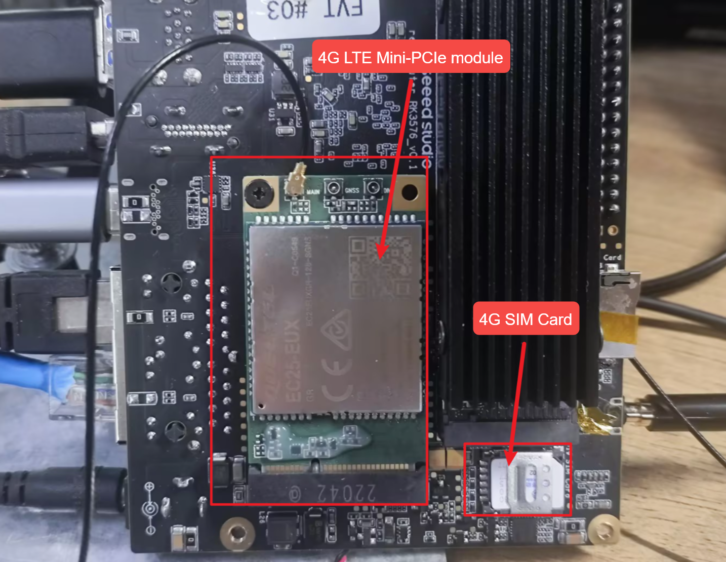
Cellular Setup via AT Commands Plug in the 4G module with the IoT SIM card, boot up the system, and verify the USB serial devices:
lsusb
ls /dev/ttyUSB*
Install and launch minicom to communicate with the module:
sudo apt install minicom
sudo minicom -D /dev/ttyUSB2
Core AT Commands Quick Reference
Detailed Status Inspection & Dialing Workflow
SIM Card Status Check: Send AT+CPIN? to verify the SIM status.
Command:  AT+CPIN?
Response: +CPIN: READY
Meaning:  The SIM card is present and ready (no PIN lock applied).
Signal Quality (RSSI) Check: Send AT+CSQ to evaluate the wireless environment.
Command:  AT+CSQ
Response: +CSQ: 28,99
Meaning:  Excellent signal. The value 28 maps to approx. -57 dBm (range 0-31, >20 is excellent). 99 indicates unknown Rx error rate (normal).
Network Registration Check: Send AT+CGREG? and AT+CREG? to check cellular attachment.
Command:  AT+CGREG?  and  AT+CREG?
Response: +CGREG: 0,1  /  +CREG: 0,1
Meaning:  The trailing 1 indicates "Registered, home network", meaning the module has successfully attached to the tower.
Current Carrier Query: Send AT+COPS? to check the operator and network mode.
Command:  AT+COPS?
Response: +COPS: 0,0,"T-Mobile",7
Meaning:  Currently attached to the specific carrier (e.g., T-Mobile). The trailing 7 indicates the connection is in LTE (4G) mode.
Data Context Activation: Query via AT+QIACT?, then activate the context using AT+QIACT=1.
Command:  AT+QIACT?   -> Response: OK (If empty, no context is currently active)
Command:  AT+QIACT=1  -> Response: OK
Meaning:  Successfully activates Context ID 1. The module will fetch a private IP from the carrier and enable cellular routing.
Note: Voice calls can be initiated via
ATD<number>;if concurrent voice/data is supported by the hardware and carrier plan.
Embedded Ping Test: Run AT+QPING to verify IP-level connectivity directly from the module.
Command:  AT+QPING=1,"www.google.com",1,4
Response: +QPING: 0["142.250.190.46",32,45,255]
          +QPING: 0,4,4,0,40,52,45
Meaning:  Successfully pinged the target domain. 4 packets sent, 4 received, 0% loss.
Troubleshooting
Lora Module Configuration & Testing Guide
USB
Verify Device Recognition
ls /dev/ttyACM*
udevadm info /dev/ttyACM0 | grep -E "ID_VENDOR|ID_MODEL"
Expected output includes:
E: ID_MODEL=STM32_Virtual_ComPort
E: ID_VENDOR=STMicroelectronics
TX Test Command
cd ~/sx1302_hal/libloragw
sudo ./test_loragw_hal_tx \
  -u \
  -d /dev/ttyACM0 \
  -r 1250 \
  -m LORA \
  -f 867.1 \
  -s 12 \
  -b 125 \
  -n 1000 \
  -z 100 \
  --dig 3 \
  --pa 0 \
  --pwid 13
Expected Output
Opening USB communication interface
INFO: Configuring TTY
INFO: Connect to MCU
INFO: Concentrator MCU version is V01.00.00
INFO: MCU status: sys_time:197172 temperature:37.2oC
Note: chip version is 0x10 (v1.0)
TX done
TX done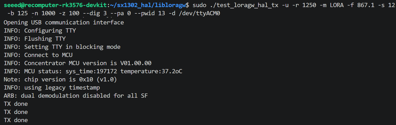
Common Errors & Fixes
| Error | Cause | Fix |
|---|---|---|
chip version is 0xFF | SPI mode used on a USB module | Add -u flag |
failed to open COM port ... No such file or directory | Device disconnected (e.g. after GPIO reset) | Replug or reboot; do not run reset_lgw.sh |
USB disconnect in dmesg | reset_lgw.sh toggled GPIO and disconnected USB | Skip the reset script for USB modules |
Note: Do not run
reset_lgw.shbefore testing USB-mode modules. The reset script toggles GPIO pins that power-cycle the module and cause USB disconnection. The STM32 MCU handles SX1302 reset internally.
SPI
Verify Device Recognition
ls /dev/ttyACM*
udevadm info /dev/ttyACM0 | grep -E "ID_VENDOR|ID_MODEL"
Expected output includes:
E: ID_MODEL=STM32_Virtual_ComPort
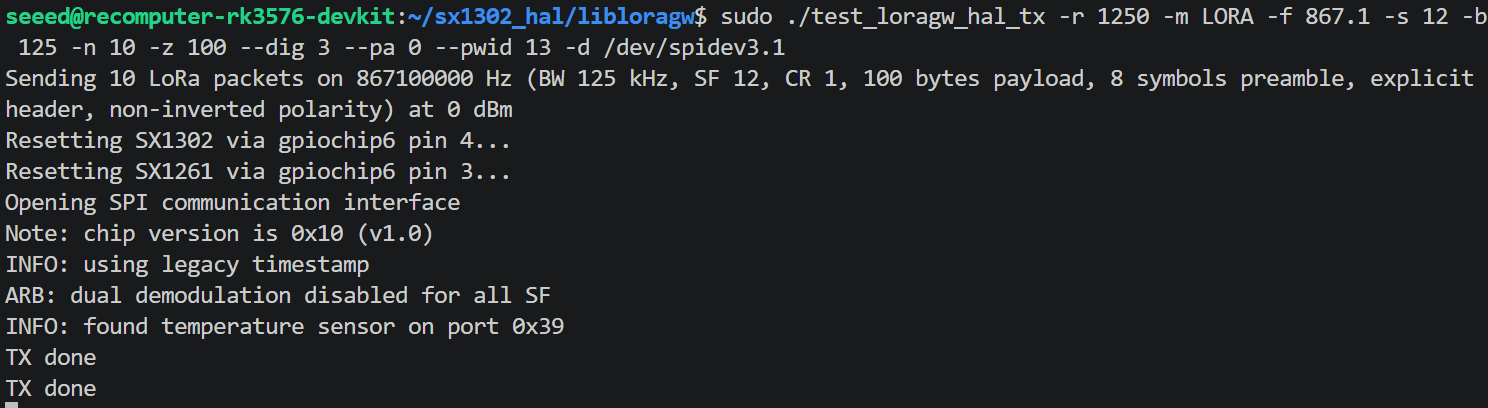
E: ID_VENDOR=STMicroelectronicsTX Test Command
cd ~/sx1302_hal/libloragw
sudo ./test_loragw_hal_tx \
  -u \
  -d /dev/ttyACM0 \
  -r 1250 -m LORA -f 867.1 -s 12 -b 125 \
  -n 1000 -z 100 --dig 3 --pa 0 --pwid 13
Expected Output
Opening USB communication interface
INFO: Configuring TTY
INFO: Connect to MCU
INFO: Concentrator MCU version is V01.00.00
INFO: MCU status: sys_time:197172 temperature:37.2oC
Note: chip version is 0x10 (v1.0)
TX done
TX done
...
HaLow WiFi Module Configuration & Testing Guide
HaLow WiFi requires a device tree overlay to expose the SPI bus and GPIO configuration for the MM6108 chip.
Add the overlay to the Armbian environment configuration:
echo "overlays=recomputer-rk3576-devkit-halow-wifi" | sudo tee -a /boot/armbianEnv.txtVerify the file before rebooting:
tail -2 /boot/armbianEnv.txtExpected output:
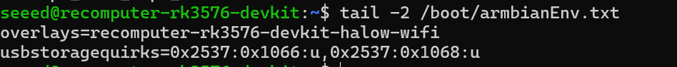
Reboot to apply the overlay:
sudo rebootAfter reboot, confirm the driver loaded and the interface appeared:
dmesg | grep -i morse | grep -E "found|Loaded|initialized|MAC"Expected output:
morse_spi spi3.1: Morse Micro SPI device found, chip ID=0x0306
morse_spi spi3.1: Loaded firmware from morse/mm6108.bin, size 459124, crc32 0x51d355b9
morse_spi spi3.1: Loaded BCF from morse/bcf_default.bin, size 1251, crc32 0x941b2a82
morse_spi spi3.1: Firmware initialized
morse_spi spi3.1: Firmware Manifest MAC: 90:03:71:52:9d:8e
The morse-hostapd and morse-wpa_supplicant binaries internally call morse_cli, but the installed binary is named morsectrl. A symlink is required.
sudo ln -s /usr/bin/morsectrl /usr/local/bin/morse_cliThis only needs to be done once.
Check interfaces:
ip link show | grep -E "wlan0|wlan1|morse0"AP Mode Create the config:
sudo nano /etc/morse-hostapd.confMinimal working configuration:
interface=wlan0
driver=nl80211
ssid=HaLow_Test
country_code=AU          # Change to your region
hw_mode=a
channel=42               # AU channel, see table below
op_class=69
beacon_int=100
dtim_period=2
ieee80211ah=1
s1g_prim_chwidth=1
s1g_prim_1mhz_chan_index=0
s1g_capab=[SHORT-GI-ALL]
wpa=2
wpa_passphrase=12345678
wpa_key_mgmt=WPA-PSK
rsn_pairwise=CCMP
ctrl_interface=/var/run/hostapd
Bring interface down and start AP:
sudo ip link set wlan0 down
sudo morse-hostapd /etc/morse-hostapd.conf -B
Expected output (success):
s1g mapped ht channel 159
Full Channel Information
    Operating Frequency: 923000 kHz
    Operating BW: 2 MHz
wlan0: interface state COUNTRY_UPDATE->ENABLED
wlan0: AP-ENABLED
Note:
Unable to set RAWwarnings are non-fatal. They appear because the installed driver version does not support RAW (Restricted Access Window). The AP starts normally.
Check AP status:
sudo morse-hostapd_cli -i wlan0 status
sudo morse-hostapd_cli -i wlan0 all_sta   # list connected clients
Station Mode Create the config:
sudo nano /etc/morse-wpa_supplicant.confMinimal configuration:
ctrl_interface=/var/run/wpa_supplicant
country=AU

network={
    ssid="HaLow_Test"
    psk="12345678"
    key_mgmt=WPA-PSK
}
Connect:
sudo ip link set wlan0 down
sudo morse-wpa_supplicant -i wlan0 -c /etc/morse-wpa_supplicant.conf -D nl80211 -B
sudo dhclient wlan0
Check connection:
sudo morse-wpa_cli -i wlan0 status
ip addr show wlan0
Ethernet RJ45
The motherboard features two independent Gigabit Ethernet (RJ45) ports. The dual-LAN design makes it ideal for building industrial edge gateways, implementing physical network isolation (intranet/extranet), or configuring complex network routing.
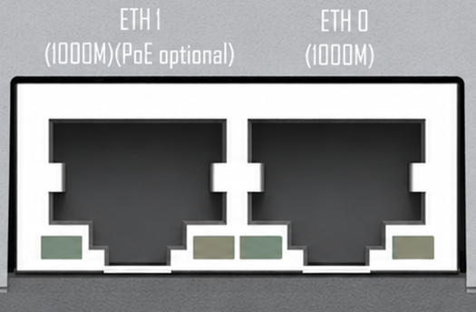
Port Definitions & Features:
- 1x Standard Gigabit Ethernet (GbE): Supports 10/100/1000 Mbps auto-negotiation Ethernet connection.
- 1x PoE-Enabled Gigabit Ethernet (GbE with PoE PD): In addition to standard Gigabit networking, this port supports the PoE PD (Powered Device) protocol.
Note: As a PoE Powered Device (PD), this RK3576 motherboard can receive power directly through the Ethernet cable from a PoE switch (PSE), eliminating the need for a separate DC power adapter.
Note:
PoE Module Requirement: The PoE power-receiving feature is not built directly into the baseboard. It requires an additional, separately purchased PoE add-on module. Without this module installed, the port functions solely as a standard Gigabit Ethernet port.
PD vs. PSE Clarification: Please note that this device acts as a PoE PD (Power Receiver). It DOES NOT support PoE output (PSE), meaning it cannot supply power to external devices like PoE IP cameras.
System Network Configuration: In Armbian OS, these two physical ports are typically enumerated as
eth0andeth1. We recommend using the standard Linux NetworkManager tool (vianmtuiornmcli) orsystemd-networkdto configure static IP addresses, network bridging, or link aggregation (bonding).
DSI
The motherboard is equipped with one 4-lane MIPI DSI (22-pin) display interface, specifically designed for connecting high-resolution embedded LCDs or industrial touch panels.
Interface Features
- High-Bandwidth Transmission: Utilizes a 4-lane physical link design, offering significantly higher data throughput compared to traditional 2-lane interfaces. It can smoothly drive 1080P or even 2K resolution HD displays.
- Physical Form Factor: Uses a 22-pin 0.5mm pitch FPC (Flexible Printed Circuit) connector with a flip-lock mechanism.
- Raspberry Pi Ecosystem Compatibility: The interface is physically backward-compatible, supporting direct connections to standard Raspberry Pi DSI screens, significantly reducing the cost and effort of sourcing accessories for developers.
DSI Configuration & Testing Guide
On the reComputer-RK3576, the MIPI DSI interface is managed via Device Tree Overlays (DTBO). Users must manually load the required overlay file based on the connected display peripheral. Open the terminal and edit the Armbian environment configuration file:
sudo nano /boot/armbianEnv.txtAdd the following line to the very end of the file to specify the DSI screen overlay:
overlays=recomputer-rk3576-devkit-raspi-7inch-touchscreenSave and exit (Press Ctrl + O, then Enter to save in nano, and Ctrl + X to exit).
Update the package lists and ensure the required multimedia and display plugins are installed:
sudo apt-get update
sudo apt install v4l-utils -y
sudo apt-get install gstreamer1.0-plugins-base gstreamer1.0-plugins-good gstreamer1.0-plugins-bad gstreamer1.0-x -y
Reboot the system to apply the changes:
sudo rebootAfter rebooting, verify whether the system successfully initialized the graphical desktop environment:
echo $XDG_SESSION_TYPENote:
If it outputs
x11orwayland, the DSI display is driven properly and has entered the graphical interface.FPC Cable Orientation: When inserting the FPC cable, pay strict attention to the orientation of the gold contacts. They must face the contact pins inside the connector. Inserting the cable backward may cause a short circuit or prevent the screen from turning on. Ensure the flip-lock is securely fastened after insertion.
Drivers & Device Tree: MIPI screens are not "plug-and-play." After connecting a display, you must enable the corresponding panel driver and backlight control nodes in Armbian OS by applying the appropriate Device Tree Overlays (e.g., using
armbian-add-overlay) or modifying the DTB files in/boot.Touch Support: This 22-pin interface typically integrates I2C signal pins for touch feedback. If you are using a MIPI touchscreen, ensure that both the display driver and the I2C touch IC driver (e.g., GT911) are loaded in the operating system.
CSI
The motherboard features two independent 4-lane MIPI CSI (22-pin) camera interfaces. Powered by the RK3576's robust ISP (Image Signal Processor) and built-in NPU, the dual CSI design is perfect for building stereo vision systems, machine vision inspection stations, or streaming high-framerate video directly for edge AI model inference.
Interface Features
- Dual 4-Lane Architecture: Provides two physical ports (
CSI_0andCSI_1), each equipped with a full 4-lane data channel, capable of handling two high-resolution or high-framerate industrial camera modules simultaneously. - Physical Form Factor: Uses a 22-pin 0.5mm pitch FPC connector.
- Raspberry Pi Ecosystem Compatibility: The 22-pin connector is physically and largely pin-compatible, supporting direct connections to standard Raspberry Pi CSI cameras (such as official or third-party modules based on IMX219 / IMX477 sensors). This allows developers to quickly validate their vision algorithms.
Note:
Compatibility & Selection: We strongly recommend using camera modules officially verified by Seeed Studio. Unverified or non-standard cameras may require developers to manually port Linux V4L2 (Video for Linux 2) drivers.
Cable Connection Standards: Pay close attention to the orientation of the FPC cable's gold contacts. Furthermore, during industrial deployment or robotics framework integration, keep in mind that MIPI signals are highly sensitive to Electromagnetic Interference (EMI). It is recommended to keep the camera ribbon cable length under 30 cm (12 inches).
Concurrent Multi-Camera Capture: In Linux, the two cameras are typically enumerated as
/dev/video0and/dev/video1. If your AI application or multimedia framework (like GStreamer or OpenCV) needs to capture both streams simultaneously, ensure proper memory bandwidth allocation and utilize hardware-accelerated plugins for optimal performance.
CSI Configuration & Testing Guide
This section guides you through enabling dual MIPI CSI cameras simultaneously (using the Raspberry Pi Camera V3 as an example). Edit the environment configuration file:
sudo nano /boot/armbianEnv.txtAdd the following line to the end of the file to enable the V3 camera drivers for both CAM0 and CAM1:
overlays=recomputer-rk3576-devkit-cam0-rpi-v3 recomputer-rk3576-devkit-cam1-rpi-v3Note: Multiple overlays must be separated by a single space. Save the file and reboot the device:
sudo rebootAfter rebooting, use the v4l-utils toolchain to verify and test the camera status.
List available camera devices and nodes:
v4l2-ctl --list-devicesView supported pixel formats and resolutions for a specific camera (e.g., /dev/video22):
v4l2-ctl --list-formats-ext --device=/dev/video22Benchmark camera frame rate: Test the streaming performance under a specific resolution and pixel format (e.g., 3280x2464 MJPG):
v4l2-ctl -d /dev/video22 --set-fmt-video=width=3280,height=2464,pixelformat='MJPG' --stream-mmap=4 --set-selection=target=crop,flags=0,top=0,left=0,width=3280,height=2464 --stream-count=500Install the GStreamer command-line tools:
sudo apt install gstreamer1.0-tools -yRun the following pipeline to preview the real-time camera feed (replace device=/dev/video11 with the actual video node index obtained from v4l2-ctl --list-devices):
gst-launch-1.0 v4l2src device=/dev/video11 ! video/x-raw,format=NV12,width=3280,height=2464HDMI
The motherboard features one standard HDMI (Type-A) port, primarily designed for connecting external monitors, televisions, or industrial control displays, providing high-definition, synchronized audio and video output.
Interface Features
- Ultra-HD Resolution: Powered by the robust multimedia capabilities of the RK3576, this interface supports up to 4K ultra-high-definition video output, ideal for rendering sharp GUI dashboards or multiple surveillance video streams.
- Audio & Video Sync: The HDMI port transmits both video and digital audio signals simultaneously. If your connected monitor has built-in speakers, system audio will play directly through the HDMI connection without requiring an additional 3.5mm audio cable.
- Multi-Display Support: This HDMI port can work concurrently with the onboard Type-C (DP 1.4) and MIPI DSI interfaces. Developers can configure cloned displays or extended desktop modes across up to three screens within the Linux OS.
Note:
Cable Standards: To ensure stability and prevent screen flickering at 4K resolutions, please strictly use high-quality cables that meet HDMI 2.0 or higher specifications.
EDID & Resolution Auto-Detection: The operating system (e.g., Armbian / Ubuntu) automatically reads the monitor's EDID information upon boot to apply the optimal resolution. If you encounter a "No Signal" issue, you can log in via SSH and use the
xrandrcommand to debug the display output status.Headless Mode Operations: If you are deploying the device purely as an edge computing node without a physical monitor, the OS may suspend desktop UI rendering to save resources. If you still need VNC remote desktop access in a headless setup, we recommend plugging a "Dummy HDMI Plug (Display Emulator)" into the port.