3.28 GPIO Input
[!IMPORTANT] This page is intended for the Seeed
reComputer J401carrier-board family, such asreComputer J4012. Do not copy the wiring blindly to a different carrier board.
Introduction
This section shows how to read a GPIO input on Jetson by connecting a test pin to GND and 3.3V and observing the input state in software.
Hardware Connection
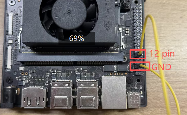
Use jumper wires to connect the header pins as shown below. A simple test method is to connect GPIO.BOARD 12 to GND first.
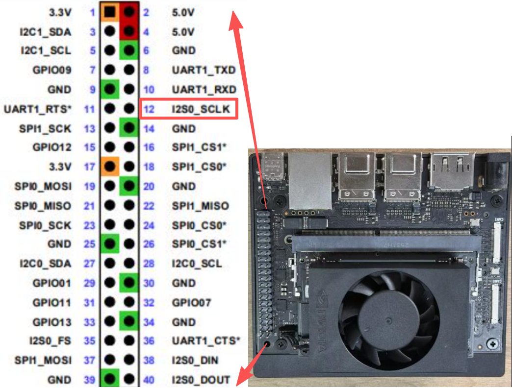
Caution: Double-check the pin mapping before wiring. Incorrect connections can short the board.
Read the Signal
Run the sample script from the jetson-gpio examples:
bash
cd /opt/seeed/development_guide/05_gpio/jetson-gpio/samples
sudo python3 simple_input.py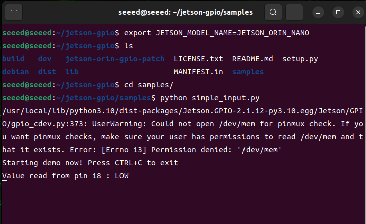
If the result matches the expected low level, reconnect the test pin from GND to 3.3V and run the script again:
bash
cd /opt/seeed/development_guide/05_gpio/jetson-gpio/samples
export JETSON_MODEL_NAME=JETSON_ORIN_NANO
python3 simple_input.py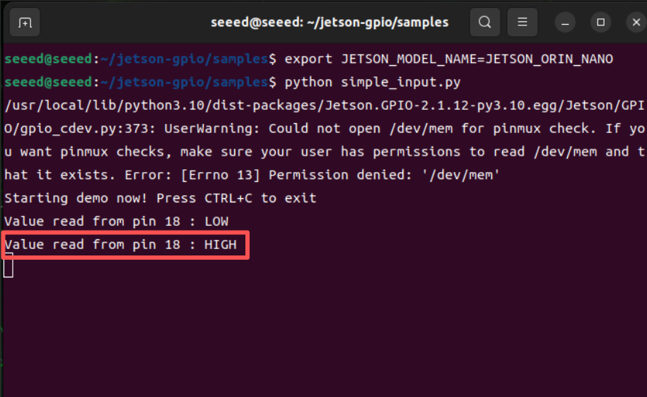
The terminal output should now report a high-level signal.