reComputer RK3588 Hardware Interfaces
Last updated:
This guide explains how to inspect and use the hardware interfaces on the reComputer RK3588 running Armbian. Use the section links to jump to the peripheral you want to connect or test.
Before you begin
- Complete first-boot setup and sign in locally or over SSH with a user that can run
sudo. - Use the port and mainboard diagrams to identify the connector before attaching a peripheral.
- Power off and disconnect the device before fitting internal cards, ribbon cables, or GPIO wiring.
- Device nodes, bus numbers, and
hwmonindices below describe the reference image. Confirm the actual devices on your system before copying a command that changes a setting.
FAN
The reComputer RK3588 exposes fan speed and PWM settings through the Linux hwmon subsystem. On the verified Armbian image, the fan is named pwmfan and appears at hwmon8. The vendor kernel also adjusts PWM using temperature thresholds from the device tree.
Hardware Monitor Paths
| Interface | Path | Description |
|---|---|---|
| Fan name | /sys/class/hwmon/hwmon8/name | pwmfan |
| Fan speed | /sys/class/hwmon/hwmon8/fan1_input | Current RPM |
| PWM value | /sys/class/hwmon/hwmon8/pwm1 | Requested PWM value, 0–255 |
| PWM enable policy | /sys/class/hwmon/hwmon8/pwm1_enable | PWM / power enable policy; observed value: 1 |
The hwmon index can change with the image or driver configuration. Confirm the name before using these paths:
for node in /sys/class/hwmon/hwmon*; do
    [ -r "$node/name" ] || continue
    printf '%s: ' "$node"
    cat "$node/name"
done
For the tested device, /sys/class/hwmon/hwmon8/name returns pwmfan.
Thermal Zones
| Zone | Reported type | Temperature path |
|---|---|---|
| SoC | soc-thermal | /sys/class/thermal/thermal_zone0/temp |
| Big Core 0 | bigcore0-thermal | /sys/class/thermal/thermal_zone1/temp |
| Big Core 1 | bigcore1-thermal | /sys/class/thermal/thermal_zone2/temp |
| Little Core | littlecore-thermal | /sys/class/thermal/thermal_zone3/temp |
| Center | center-thermal | /sys/class/thermal/thermal_zone4/temp |
| GPU | gpu-thermal | /sys/class/thermal/thermal_zone5/temp |
| NPU | npu-thermal | /sys/class/thermal/thermal_zone6/temp |
Temperature values are in millidegrees Celsius. Divide by 1000 to obtain °C. This image has seven thermal zones; use the reported names rather than copying the RK3576 zone numbers.
Reading Fan Speed and Temperature
cat /sys/class/hwmon/hwmon8/fan1_input
cat /sys/class/hwmon/hwmon8/pwm1
cat /sys/class/hwmon/hwmon8/pwm1_enable
After the test settings were restored, the readings were approximately 2280 RPM, PWM 25, and enable policy 1. These are observations, not fixed values for every device.
Read all temperature zones:
for zone in /sys/class/thermal/thermal_zone*; do
    [ -r "$zone/type" ] && [ -r "$zone/temp" ] || continue
    printf '%s: ' "$(cat "$zone/type")"
    awk '{printf "%.1f°C\n", $1 / 1000}' "$zone/temp"
done
The observed SoC temperature was approximately 37°C.
Short PWM Write Test
Single writes of 64, 128, and 255 were tested. Each requested value could be read immediately after writing, but the vendor temperature controller restored PWM to 25 within approximately one second at the observed temperature.
| Requested PWM | Immediate reading in the test | Reading after approximately one second |
|---|---|---|
| 64 | 64 | 25 |
| 128 | 128 | 25 |
| 255 | 255 | 25 |
For a short check, save the current value, request 128, read it back, and restore the saved value:
FAN_PWM=/sys/class/hwmon/hwmon8/pwm1
ORIGINAL_PWM=$(cat "$FAN_PWM")
printf '128\n' | sudo tee "$FAN_PWM"
cat "$FAN_PWM"
sleep 1
cat "$FAN_PWM"
printf '%s\n' "$ORIGINAL_PWM" | sudo tee "$FAN_PWM"
If the first read already returns the temperature-controlled value, the kernel may have overwritten the request before the read completed. A successful write does not establish sustained manual control, and these test values do not demonstrate fixed 25%, 50%, or full fan speeds.
Vendor Temperature Control
The tested device tree contains the following cooling-levels and rockchip,temp-trips configuration:
| Temperature range (°C) | Cooling level | PWM value |
|---|---|---|
| <38 | 0 | 25 |
| 38–<44 | 1 | 45 |
| 44–<50 | 2 | 60 |
| 50–<56 | 3 | 75 |
| 56–<62 | 4 | 100 |
| 62–<68 | 5 | 130 |
| 68–<74 | 6 | 170 |
| 74–<80 | 7 | 210 |
| ≥80 | 8 | 255 |
Inspect the active device-tree configuration:
python3 - <<'PY'
from pathlib import Path
import struct

node = Path('/sys/firmware/devicetree/base/pwm-fan')
for name in ('cooling-levels', 'rockchip,temp-trips'):
    data = (node / name).read_bytes()
    values = struct.unpack('>' + 'I' * (len(data) // 4), data)
    print(name + ':', list(values))
PY
On this image, pwm1_enable=1 does not disable vendor temperature control. Do not treat this attribute as a universal 1=manual, 2=automatic switch. Its PWM / power policy is described in the Linux pwm-fan documentation; the Rockchip temperature callback is implemented in the vendor driver.
The device continued temperature control after the test. No separate temperature-control script or systemd service was installed. Taking over the vendor controller and running a custom service have not yet been verified for this device.
Quick Reference
cat /sys/class/hwmon/hwmon8/name
cat /sys/class/hwmon/hwmon8/fan1_input
cat /sys/class/hwmon/hwmon8/pwm1
cat /sys/class/hwmon/hwmon8/pwm1_enable
awk '{printf "%.1f°C\n", $1 / 1000}' /sys/class/thermal/thermal_zone0/temp
Verified Environment
| Item | Value |
|---|---|
| Device | reComputer RK3588 |
| OS | Armbian 26.8.7 / Ubuntu 26.04 (resolute), ARM64 |
| Kernel | 6.1.172-vendor-seeed-rk3588 |
| Fan monitor | /sys/class/hwmon/hwmon8 (pwmfan) |
| PWM after restoration | 25 |
| Enable policy after restoration | 1 |
| Observed fan speed after restoration | Approximately 2280 RPM |
| Observed SoC temperature | Approximately 37°C |
LED Indicator Status
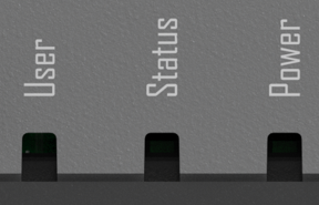
The device has Power, Status, and User indicators. The User indicator is an RGB LED.
LED Behavior and Control
| Indicator | Default behavior | Control |
|---|---|---|
| Power (red) | Stays on when power is connected | Hardware power circuit |
| Status (green) | Driven by the onboard power status circuit | No corresponding LED class control node is exposed by the current system |
| User (RGB) | Blue heartbeat; red and green off | All three color channels can be controlled through the Linux LED class |
Locate the LEDs
The current RK3588 image exposes these nodes. All three channels have a max_brightness value of 1:
| Color | Node | Default trigger |
|---|---|---|
| Red | /sys/class/leds/user-led_red | none |
| Green | /sys/class/leds/user-led_green | none |
| Blue | /sys/class/leds/user-led_blue | heartbeat |
ls -d /sys/class/leds/user-led_*
cat /sys/class/leds/user-led_blue/trigger
cat /sys/class/leds/user-led_blue/max_brightness
Square brackets in the trigger output mark the active trigger, for example [heartbeat].
Manual Control (On / Off)
Set the trigger to none before writing brightness. Use 1 for on and 0 for off:
LED_PATH=/sys/class/leds/user-led_blue
echo none | sudo tee "$LED_PATH/trigger"
echo 1 | sudo tee "$LED_PATH/brightness"
sleep 2
echo 0 | sudo tee "$LED_PATH/brightness"
For red or green, replace user-led_blue at the end of the path with user-led_red or user-led_green. The LED driver manages all three channels, so gpioset is unnecessary.
Automatic Triggers
Make the blue channel alternate between 500 ms on and 500 ms off:
LED_PATH=/sys/class/leds/user-led_blue
echo timer | sudo tee "$LED_PATH/trigger"
echo 500 | sudo tee "$LED_PATH/delay_on"
echo 500 | sudo tee "$LED_PATH/delay_off"
Restore the blue heartbeat trigger:
echo heartbeat | sudo tee /sys/class/leds/user-led_blue/triggerRestore the Default State
for color in red green; do
    LED_PATH="/sys/class/leds/user-led_$color"
    echo none | sudo tee "$LED_PATH/trigger"
    echo 0 | sudo tee "$LED_PATH/brightness"
done
echo heartbeat | sudo tee /sys/class/leds/user-led_blue/trigger
These settings affect the running system without changing its startup configuration. See the Linux LED documentation for brightness and trigger behavior.
Buttons
The mainboard provides Power, Recovery, and MaskROM buttons. For firmware operations, use a USB data cable connected to the Type-C OTG port and follow the flashing instructions for the selected RK3588 image. Recovery and MaskROM are flashing modes, not normal desktop startup steps.
GPIO and Peripheral Buses
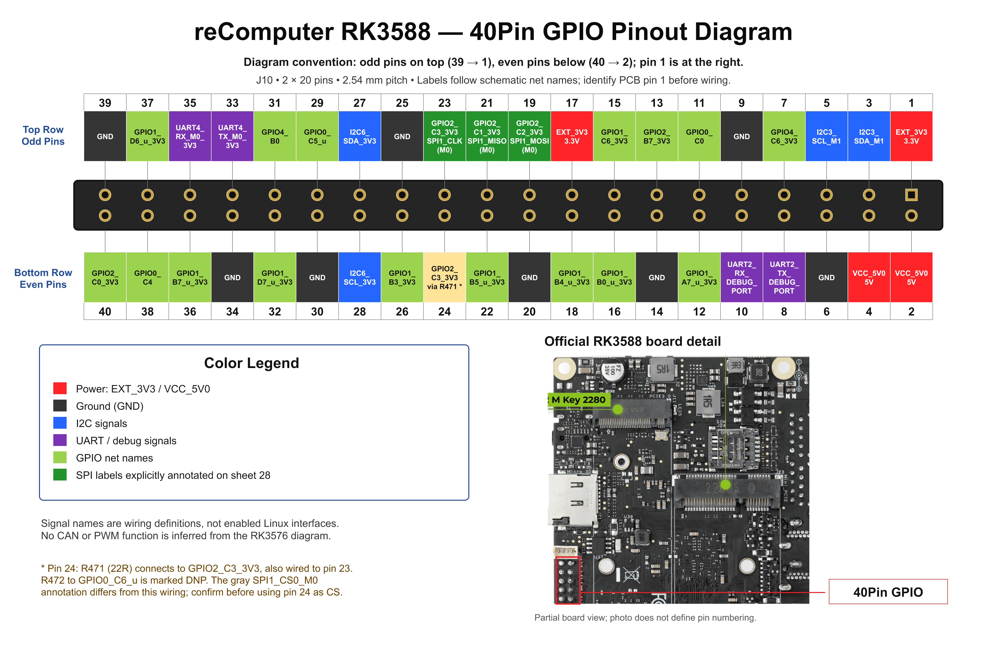
Check the controllers and line names exposed by the current device tree:
gpiodetect
gpioinfo
If these tools are unavailable, install the distribution package:
sudo apt update
sudo apt install gpiod
Use the RK3588 schematic to match physical pins to signals, then locate the corresponding controller and line in gpioinfo. Check gpioset --help for the installed libgpiod command syntax before setting an output.
List the installed RK3588 overlays and current boot configuration:
find /boot -type f -name '*rk3588*.dtbo' -print
grep -E '^(fdtfile|overlay_prefix|overlays|user_overlays)=' /boot/armbianEnv.txt
For I2C, UART, SPI, or CAN, select an overlay supplied for your board and connected peripheral. Preserve existing overlays when editing /boot/armbianEnv.txt; the installed overlay's documentation defines its parameters and pin assignments.
USB
The Seeed Studio specifications list the following USB interfaces for reComputer RK3588:
| Interface / quantity | Physical connector | Bus protocol and functions | Uses |
|---|---|---|---|
| USB 3.0 Host ×4 | USB Type-A | USB 3.0, nominal signaling rate of 5 Gbps | Connect USB cameras, external storage, keyboards, mice, and other peripherals. |
| USB Type-C ×1 | USB Type-C | OTG + DisplayPort | OTG device connections and DisplayPort output, using a cable or adapter that supports the required function. |
5 Gbps is the nominal USB 3.0 signaling rate, not a measured file-transfer speed. It does not establish independent 5 Gbps controller bandwidth for each of the four Type-A ports.
List connected USB devices and their topology:
lsusb
lsusb -t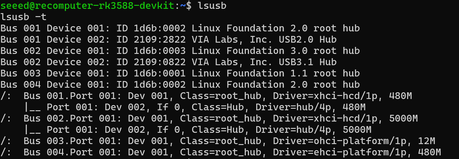
Use lsusb -t to inspect the negotiated connection speed. For a USB camera or accelerator, also follow the peripheral's driver and application instructions.
microSD and NVMe Storage
The device has a microSD slot and PCIe expansion for NVMe SSDs. Identify the storage device by model, capacity, and mount point before using it:
lsblk -o NAME,MODEL,SIZE,TYPE,FSTYPE,MOUNTPOINTS
lspci -nn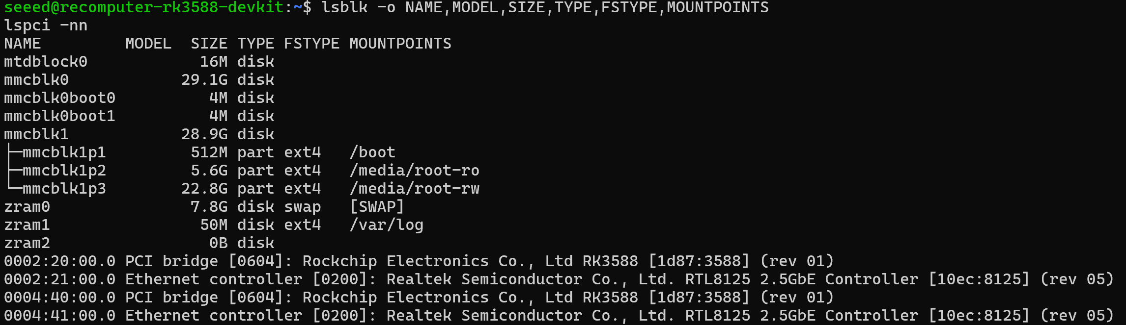
For an NVMe SSD, check its PCIe link and driver:
lspci -nnk | grep -A 3 -i 'Non-Volatile memory'A detected drive does not by itself establish boot support; use the installation procedure supplied with the selected image.
M.2 Expansion Interfaces
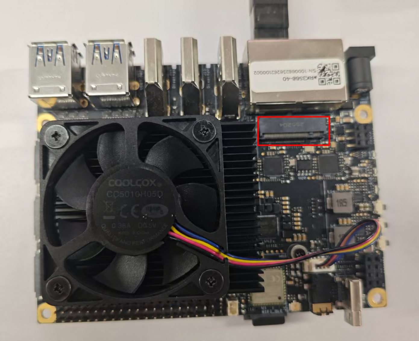
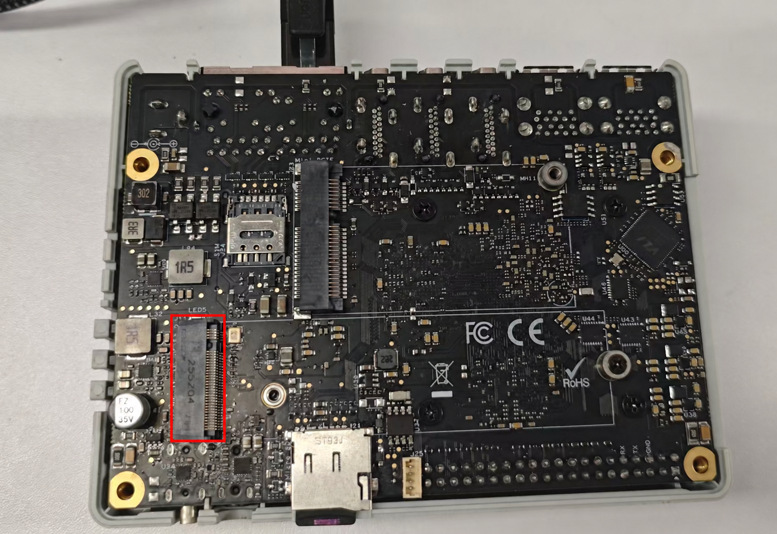
reComputer RK3588 provides two M.2 Key-M interfaces for NVMe storage or compatible PCIe AI accelerator modules.
| Module size | PCIe specification |
|---|---|
| 2242 (22 × 42 mm) | PCIe 2.1 ×1 |
| 2280 (22 × 80 mm) | PCIe 3.0 ×4 |
×1 and ×4 denote one lane and four lanes. PCIe 2.1 ×1 follows the official product listing for the 2242 interface. Check the module key, length, and mounting position when selecting a slot. The currently negotiated speed and width can be checked using LnkSta below. See the Seeed Studio product details.
M.2 Key-M 2242 interface (PCIe 2.1 ×1)
M.2 Key-M 2280 interface (PCIe 3.0 ×4)
Install a module
- Shut down the system and disconnect DC or PoE power before opening the enclosure.
- Confirm that the module key, length, and mounting position match the slot. Insert the module and secure it with a screw.
- Check cooling and connections, then reconnect power and boot the system.
Select an NVMe SSD for storage; an AI accelerator also requires drivers and a runtime matching the RK3588 operating system and kernel. Use the earlier lsblk command to inspect storage capacity.
Identify PCIe devices and drivers
lspci -nnkFind the SSD or accelerator entry and inspect its device address, model, and Kernel driver in use.
Check negotiated link speed and width
Enter the PCIe device address from the preceding output when prompted:
read -rp 'PCIe device address: ' PCIE_DEVICE
sudo lspci -s "$PCIE_DEVICE" -vv | grep -E 'LnkCap:|LnkSta:'
LnkCap reports the device's link capabilities; LnkSta reports the currently negotiated speed and width. For NVMe system boot, configure the boot environment using the installation procedure for your Armbian image.
SIM and miniPCIe Expansion
The nano SIM slot is used with a compatible cellular module. Disconnect device power before inserting the SIM or installing an internal module. miniPCIe supports optional 4G LTE, LoRaWAN, or Wi-Fi HaLow modules; select the matching antenna and software for the module.
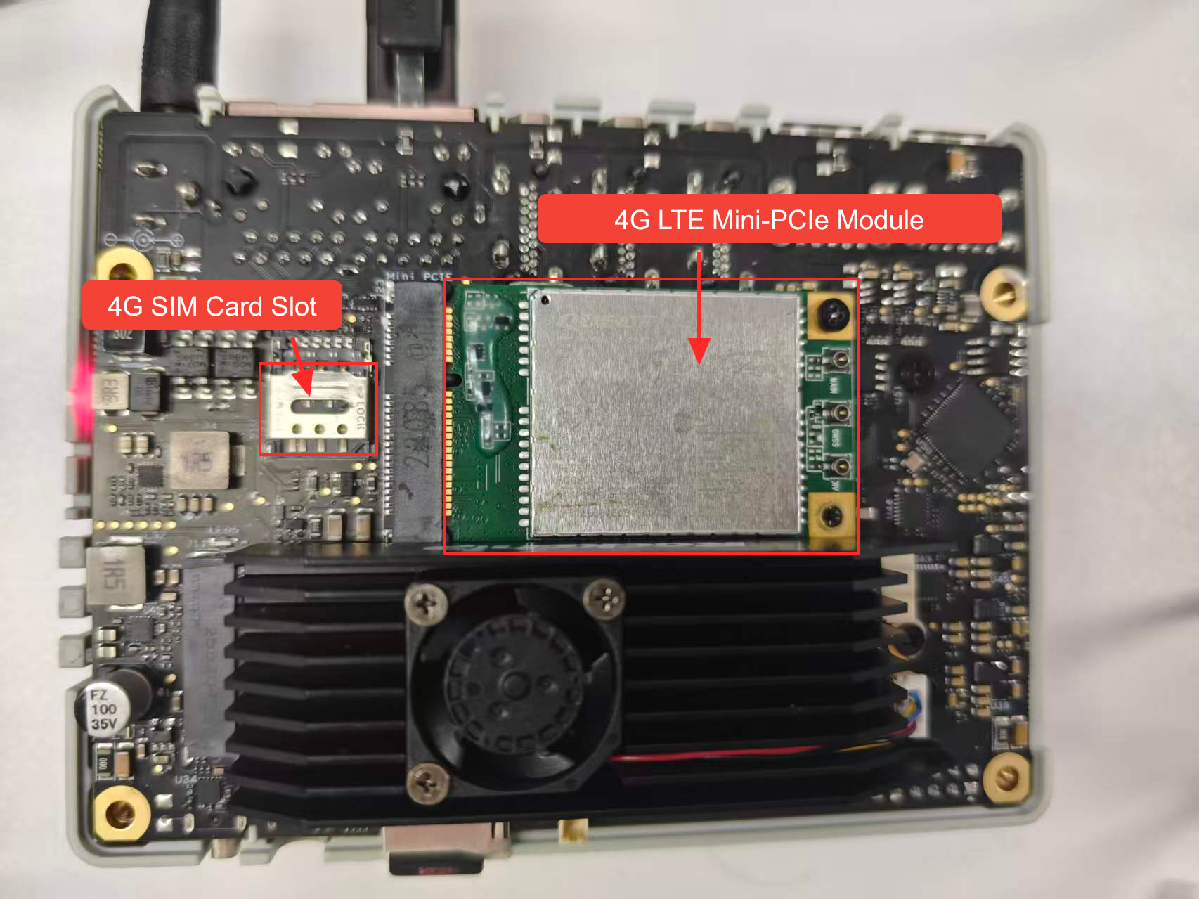
After installing a module and starting the system, inspect its PCIe, USB, and network enumeration:
lspci -nn
lsusb
ip -br link
4G Module (EC25) Queries
For a USB cellular module such as EC25, first identify serial devices and driver messages:
ls /dev/ttyUSB*
sudo dmesg | grep -iE 'quectel|option|ttyUSB|qmi_wwan|cdc_ether' | tail -n 50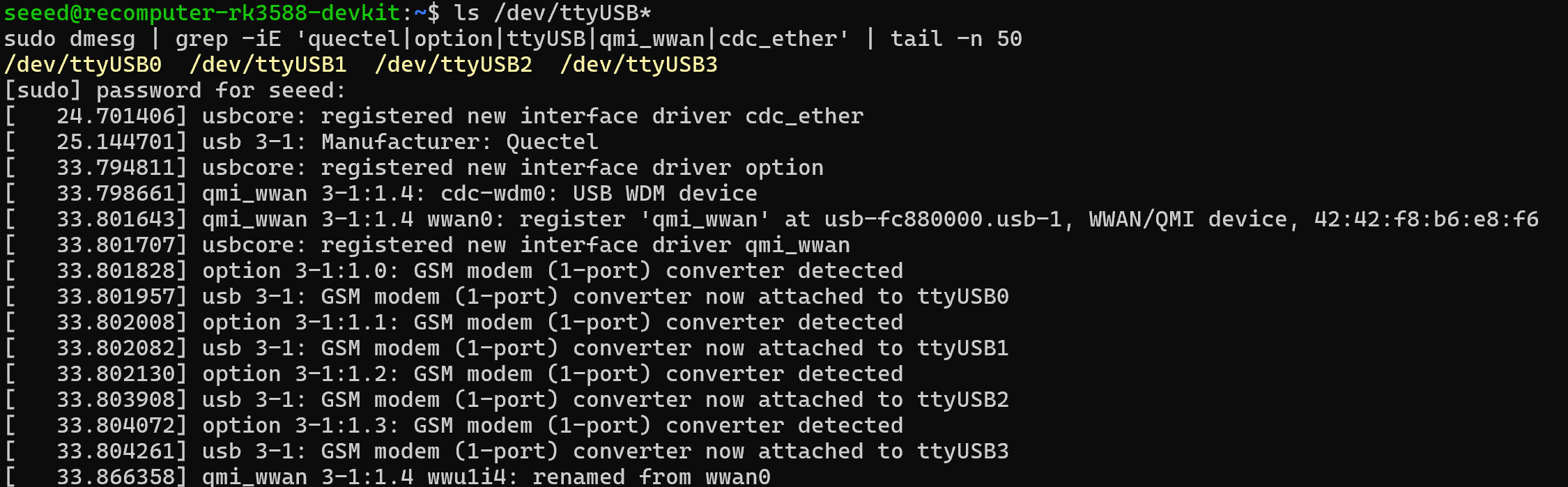
Identify the AT command port using the module documentation, then install and open minicom. /dev/ttyUSB2 in the prompt is only an example; enter the actual AT port on your device:
sudo apt update
sudo apt install minicom
read -rp 'AT serial device (e.g. /dev/ttyUSB2): ' AT_PORT
sudo minicom -D "$AT_PORT" -b 115200
Send the following commands individually inside minicom, not in the Linux shell. Send AT first and continue after receiving OK:
AT
ATI
AT+CPIN?
AT+CSQ
AT+CREG?
AT+CGREG?
AT+CEREG?
AT+COPS?
ATI reads module information, AT+CPIN? checks SIM status, AT+CSQ reads signal quality, AT+CREG?, AT+CGREG?, and AT+CEREG? check registration, and AT+COPS? reads the current operator. Press Ctrl+A, then X to exit minicom. See the Quectel EC25 / EC21 AT Commands Manual.
Data connectivity also requires host networking configured for the carrier APN and the module's USB data mode. A ready SIM or registered module does not by itself establish Internet access on RK3588.
LoRaWAN and Wi-Fi HaLow Interface Discovery
For the installed USB or SPI module, inspect device nodes, existing overlay settings, and driver messages:
lsusb
ls /dev/ttyACM*
ls /dev/spidev*
find /boot -type f -name '*.dtbo' | grep -iE 'halow|lora|rk3588'
grep -E '^(fdtfile|overlay_prefix|overlays|user_overlays)=' /boot/armbianEnv.txt
sudo dmesg | grep -iE 'morse|mm6108|sx1302|lora' | tail -n 50
ip -br link
USB and SPI modules use different transports. Select LoRaWAN test arguments, SPI / GPIO reset settings, and HaLow overlays from the RK3588 image and module documentation, rather than reusing RK3576 overlay names. Follow the module-specific guide for gateway transmission/reception and HaLow AP / station configuration.
Ethernet RJ45
reComputer RK3588 provides two RJ45 2.5GbE Ethernet ports. They can connect an upstream network and local devices for edge gateways, device data acquisition, or applications requiring two network ports.
One port can power the device through an additional PoE module. Install the matching module and check the power requirements of the switch or power sourcing equipment before using PoE.
Identify network interfaces and IP addresses
Connect the Ethernet cable, then list interface names and addresses on the current system:
ip -br link
ip -br addr
Use the names reported by the system rather than assuming eth0 or eth1. To map the two physical ports to interface names, connect or disconnect each cable separately and observe the corresponding link-state change.
Check negotiated speed and link status
Install ethtool and enter the wired interface name identified above when prompted:
sudo apt update
sudo apt install ethtool
read -rp 'Ethernet interface: ' ETH_IFACE
sudo ethtool "$ETH_IFACE"
Inspect Speed, Duplex, and Link detected. Link detected: yes indicates a physical link; Speed: 2500Mb/s indicates a negotiated 2.5GbE connection. The device port, connected switch or adapter, and cable determine the actual link rate.
Configure network connections
On images using NetworkManager, inspect connections and open the text interface to configure DHCP or a static IP:
nmcli device status
nmtui
In nmtui, select the wired connection, configure its IP address, gateway, and DNS, and activate it according to the network plan. Configure the two connections separately when using both ports.
Wi-Fi and Bluetooth
The device includes onboard Wi-Fi 6 and Bluetooth 5.4. Inspect radio blocking and the Bluetooth controller:
rfkill list
bluetoothctl list
HDMI and DisplayPort
The device provides two HDMI 2.1 outputs, one HDMI 2.0 input, and DisplayPort through Type-C. Connect monitors to the output ports. HDMI input is used for capture from a separate video source.
Check display connector status:
for connector in /sys/class/drm/card*-*; do
    [ -r "$connector/status" ] || continue
    printf '%s: ' "$connector"
    cat "$connector/status"
    [ ! -r "$connector/modes" ] || cat "$connector/modes"
done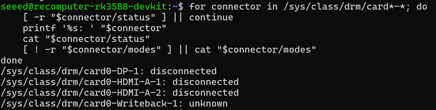
For capture devices, including HDMI input or a supported camera, list the video devices with V4L2:
sudo apt install v4l-utils
v4l2-ctl --list-devices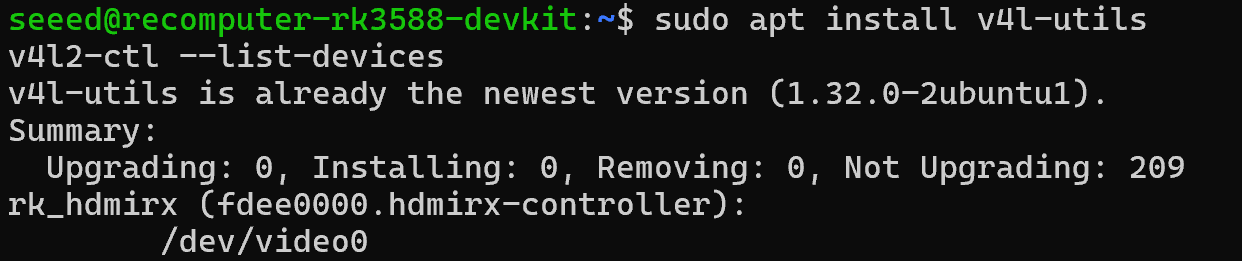
Use the reported video node and supported formats for capture. Configure multiple displays in the desktop's display settings.
RTC
The mainboard provides a 2-Pin RTC connector. Confirm polarity and battery requirements in the schematic before connecting a battery. Check the RTC devices exposed by Linux:
for rtc in /sys/class/rtc/rtc*; do
    [ -r "$rtc/name" ] || continue
    printf '%s: ' "$rtc"
    cat "$rtc/name"
    [ ! -r "$rtc/date" ] || cat "$rtc/date"
    [ ! -r "$rtc/time" ] || cat "$rtc/time"
done
Hardware documents and system images are available in the resource download summary.