Device Setup
The Device Setup page contains five steps.
Device Pairing
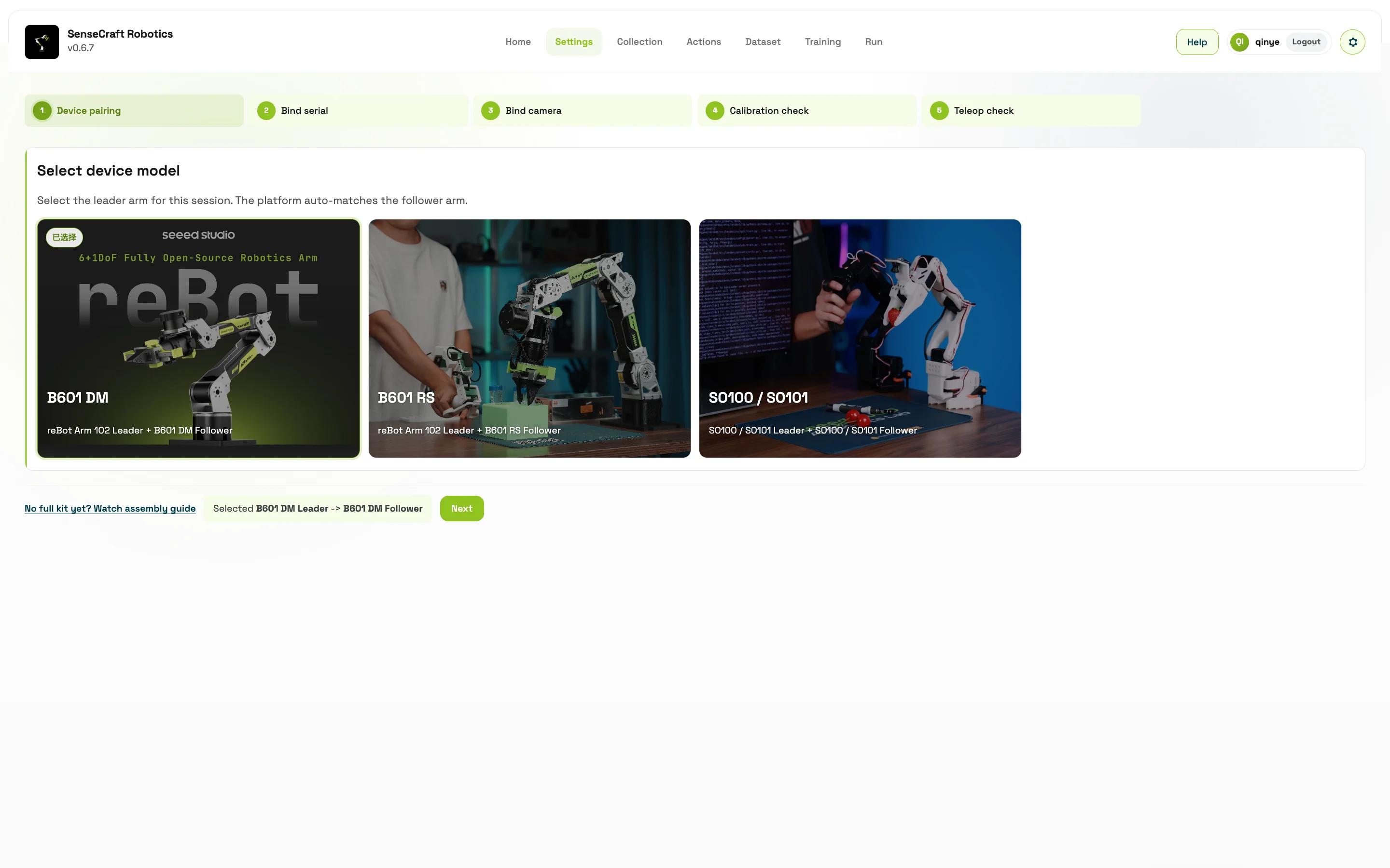
Section titled “Device Pairing”Select the robotic arm model currently in use:
- B601 DM
- B601 RS
- SO100 / SO101
After selection, the platform matches the corresponding leader arm and follower arm.
SO100 / SO101 selection. SO100 and SO101 share the SO100 / SO101 device option in the software and do not need to be distinguished further. Select this option, then continue binding the leader and follower arms.
Bind Serial Port / CAN
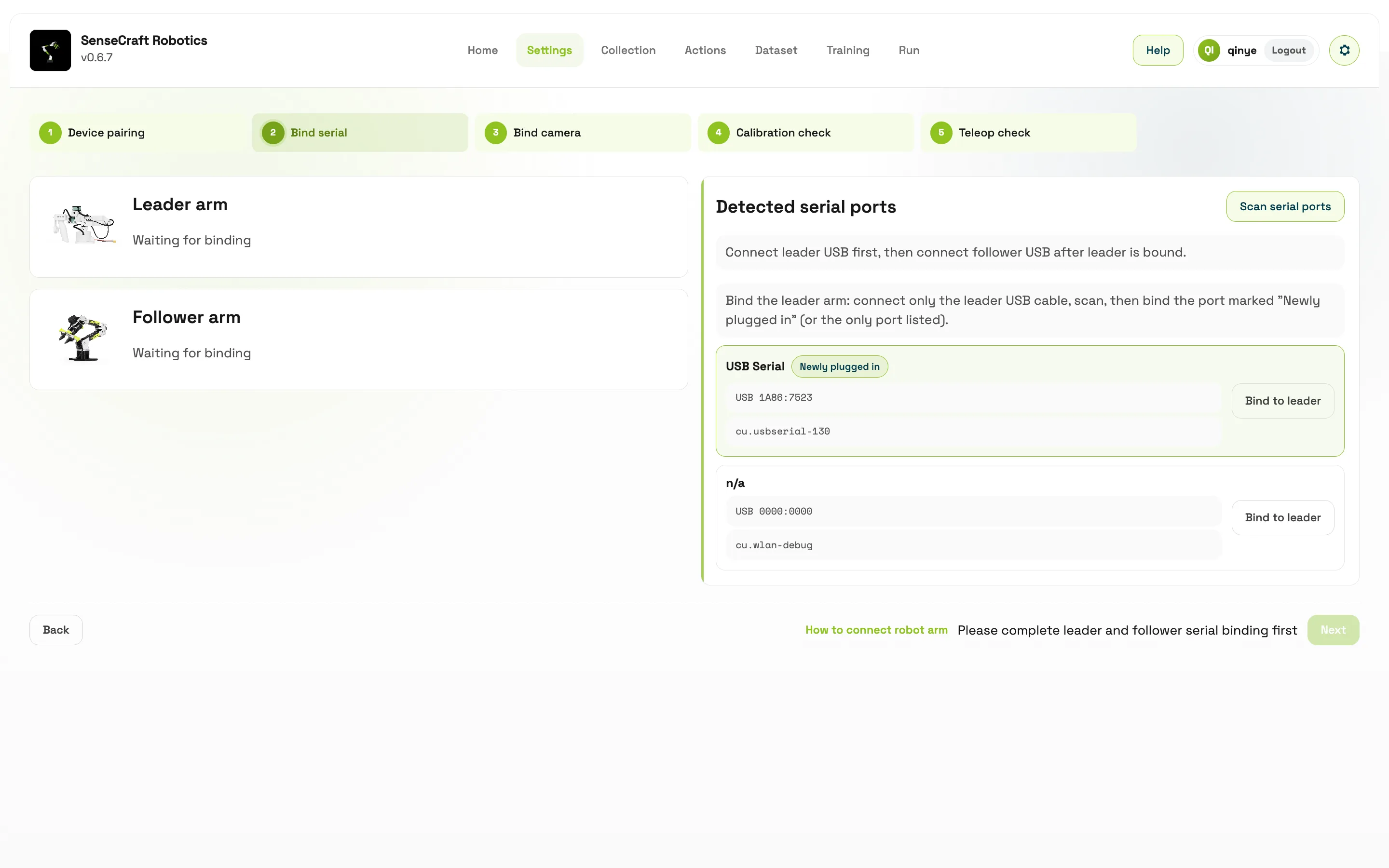
Section titled “Bind Serial Port / CAN”The serial port names for the leader and follower arms may be identical or difficult to distinguish. To avoid reversing the bindings, connect and scan them in two stages:
Recommended operation:
- Connect the leader arm USB cable first.
- Scan the serial ports and bind the newly detected port as the leader arm.
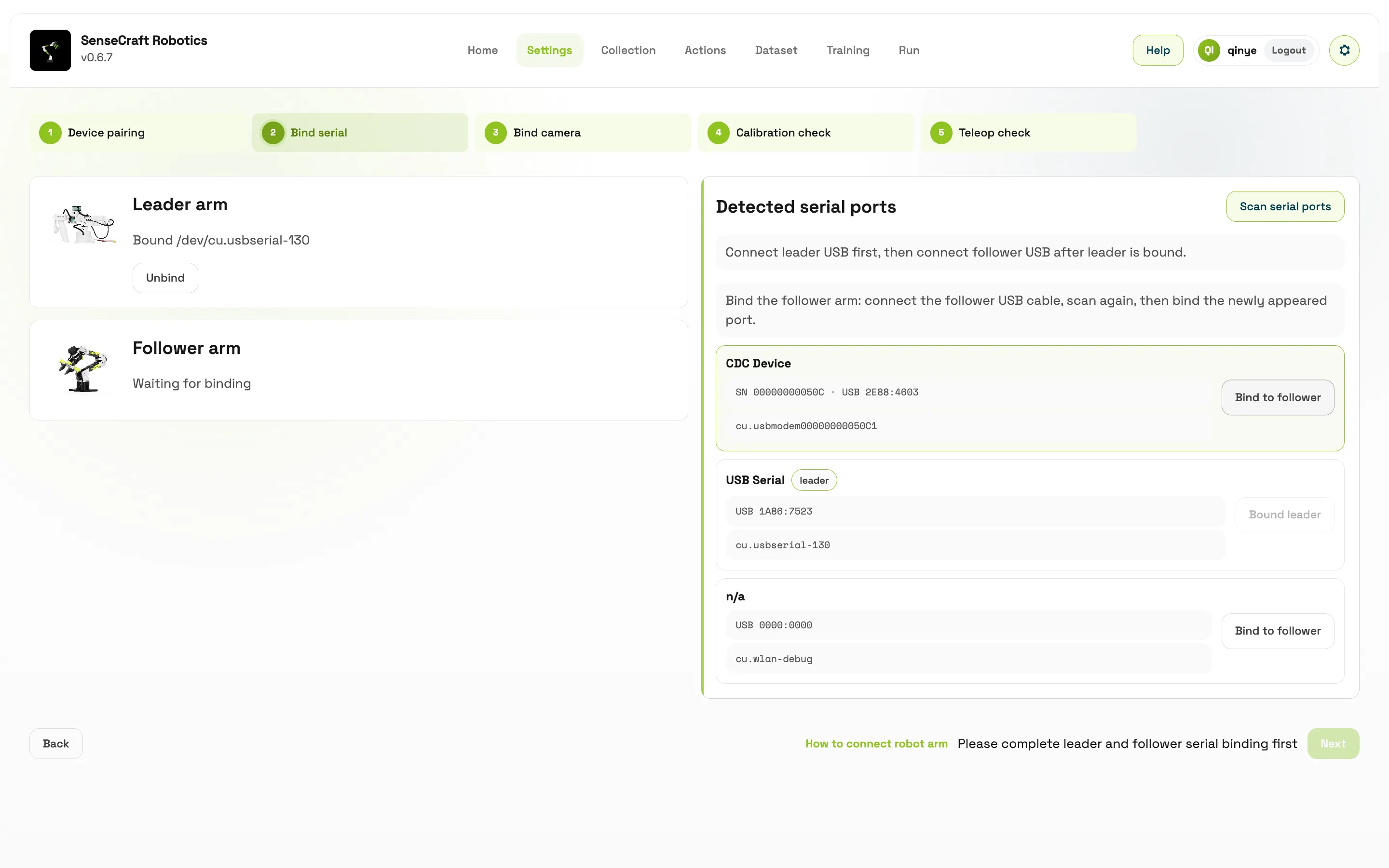
- Connect the follower arm, then scan the serial ports again.
- Bind the newly detected port as the follower arm and confirm that both arms are shown as bound.
For B601 RS, the CAN interface panel will be displayed:
- Linux / Jetson can scan SocketCAN interfaces such as
can0. - macOS / Windows will check the PCAN runtime. Enter a channel name manually if needed.
- The follower arm CAN channel can be bound manually.
If the system reports insufficient serial port permissions, use the authorization flow provided on the page.
Bind Cameras
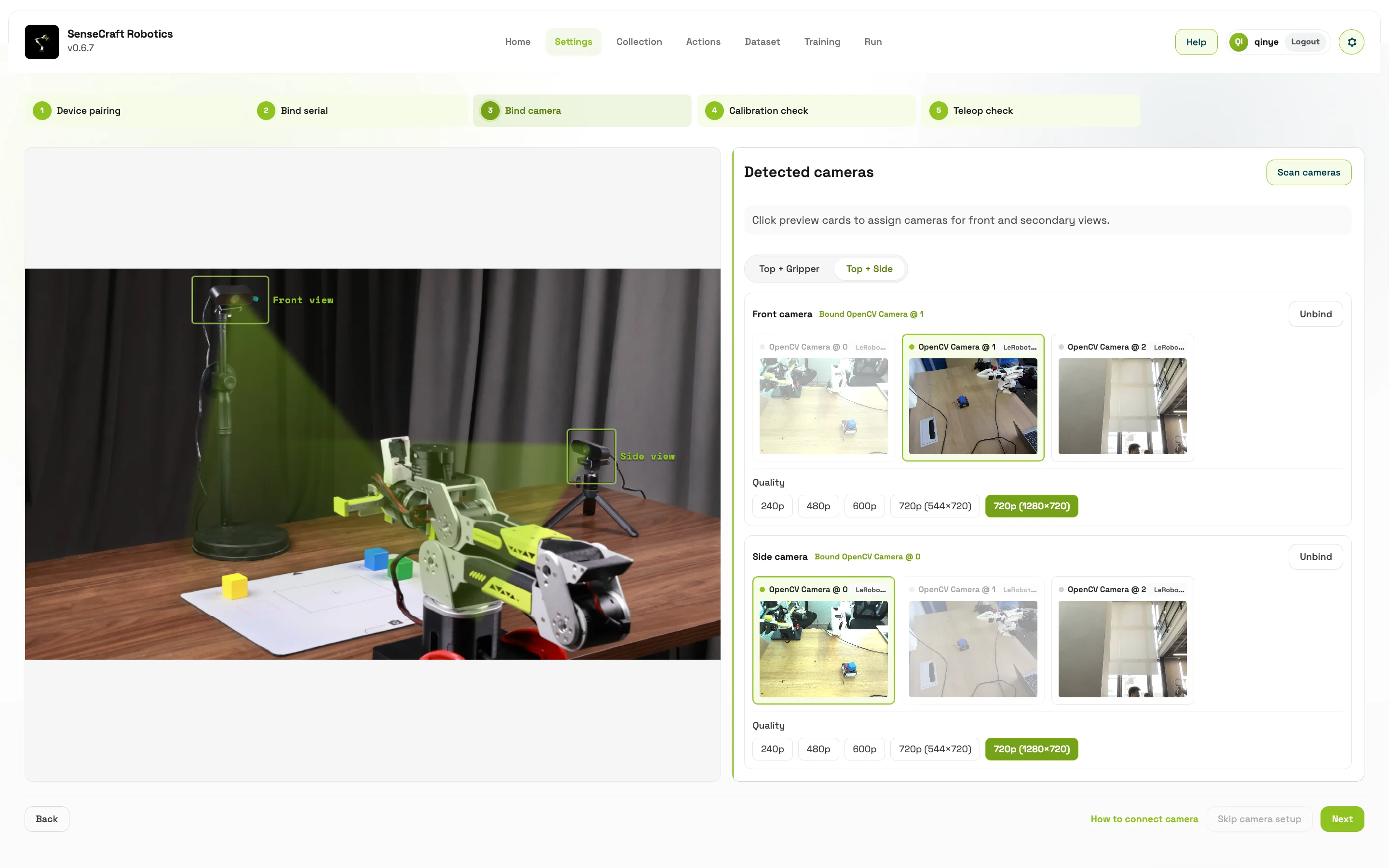
Section titled “Bind Cameras”In the camera step:
- Select the camera layout: top view + gripper view, or top view + side view.
- Click Scan Cameras.
- Select the device for the top-view camera.
- Select the device for the second view.
- Choose image quality, resolution, and frame rate based on available modes.
If the current task only needs teleoperation and does not require visual data collection, click Skip Camera Setup.
Training and visual inference usually require camera data, so camera binding is recommended before formal data collection. Both the Collection and Run pages support live camera preview, preview refresh, preview enable, and preview disable.
| Layout | Purpose |
|---|---|
| Top view + side view | Observe the workspace from above and from the side |
| Top view + gripper view | Observe operation from above and from the gripper perspective |
Camera Placement Recommendations
Section titled “Camera Placement Recommendations”Use the following positions as starting points for the first setup. Adjust the actual distance and angle according to the lens field of view, workbench size, and task area.
- Start with cameras approximately 30–80 cm from the workbench. Make sure the target objects, gripper, and key motion areas are clearly visible.
- Place an external camera approximately 45° to the left or right of the front of the workspace as a starting point, avoiding overly flat views and mutual occlusion of key actions.
- Keep lighting even and avoid strong reflections, obvious shadows, and frequently changing ambient light.
- A top-view camera should cover as much of the complete arm travel and target positions as possible. A side-view camera should clearly show the object, the gripper approach, and the task completion position.
- Cameras, mounts, and cables must remain outside the arm’s motion path. Secure gripper-camera cables so they are not pulled or obstruct the image during motion.
Robotic Arm Calibration
Section titled “Robotic Arm Calibration”Before calibration, return the leader arm and follower arm to the recommended posture. The page guides the process based on the calibration strategy of the selected device.
Common flow:
- Click Start Calibration.
- Follow the prompts to complete stages such as leader arm neutral position, leader arm servo calibration, follower arm neutral position, and follower arm servo calibration.
- After each stage is complete, click Confirm and Continue.
- If the posture is incorrect or the device behaves abnormally, click Stop Calibration and start again.
SO series devices usually use joint range calibration. B601 series devices usually use mechanical zero-position calibration.
SO Series Calibration Methods
Section titled “SO Series Calibration Methods”SO series devices may provide automatic and manual calibration. Follow the calibration mode shown for the current device and page.
- Automatic calibration. Before starting, leave sufficient space around the arm and confirm that the wrist and relevant joints have the mechanical stops required by the device. If you cannot confirm the stop configuration, do not start automatic calibration. Use manual calibration or contact technical support to avoid cable or structural damage from continuous joint rotation.
- Manual calibration. Typically, first confirm the leader arm’s neutral position, then move each leader-arm joint as instructed to calibrate its motion range. Repeat the neutral-position confirmation and joint-range calibration for the follower arm. Move each joint slowly through the permitted range and do not force it against a mechanical stop.
Calibration Troubleshooting
Section titled “Calibration Troubleshooting”If an error appears immediately after clicking Start Calibration, or the follower stage fails after the leader arm is calibrated, check the following in order:
| Symptom | Check first |
|---|---|
| Robotic arm joint abnormality is reported | Confirm that the device is powered on and the power supply is normal. Make sure the model selected in the software matches the actual arm. |
| Leader or follower arm does not respond | Check whether the leader and follower ports are reversed, whether the serial port remains connected, and whether the USB / CAN cables and arm wiring are secure. |
| Serial write failure or device recognition error | Stop calibration and recheck port binding and cable connections. Rescan and bind the device if necessary before restarting. |
| Leader calibration succeeds but follower calibration fails | Focus on the follower arm’s power, port, and cables. Do not repeatedly force calibration to continue. |
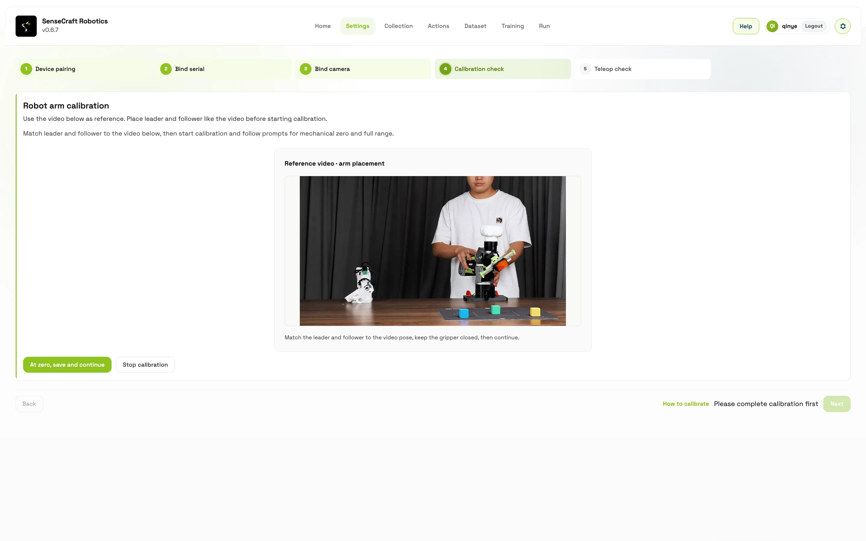
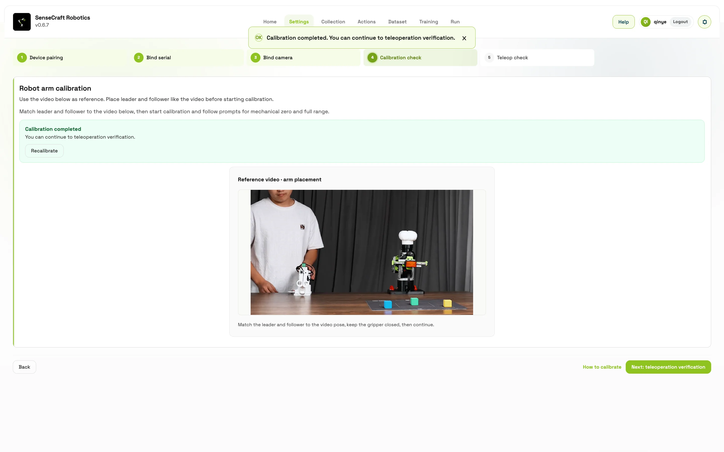
Teleoperation Verification
Section titled “Teleoperation Verification”Teleoperation is used to confirm the connection, direction, and following relationship between the leader arm and follower arm:
- Click Start Teleoperation.
- Move the leader arm slowly and within a small range.
- Observe whether the follower arm follows steadily in the same direction.
- If the behavior is normal, select Normal and proceed to data collection.
- If the follower arm does not follow, moves in the opposite direction, or stutters, select Abnormal and return to check connection and calibration.
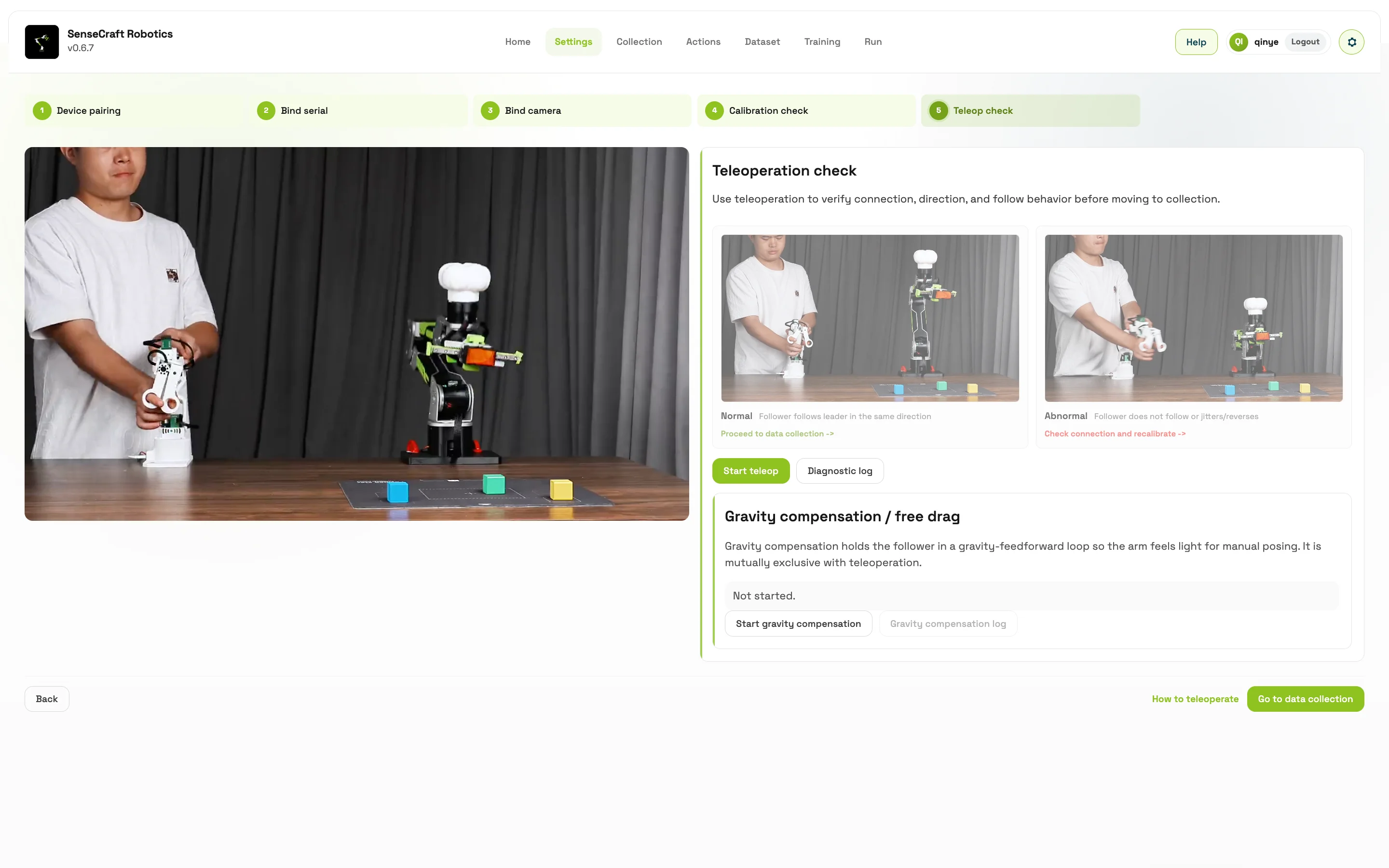
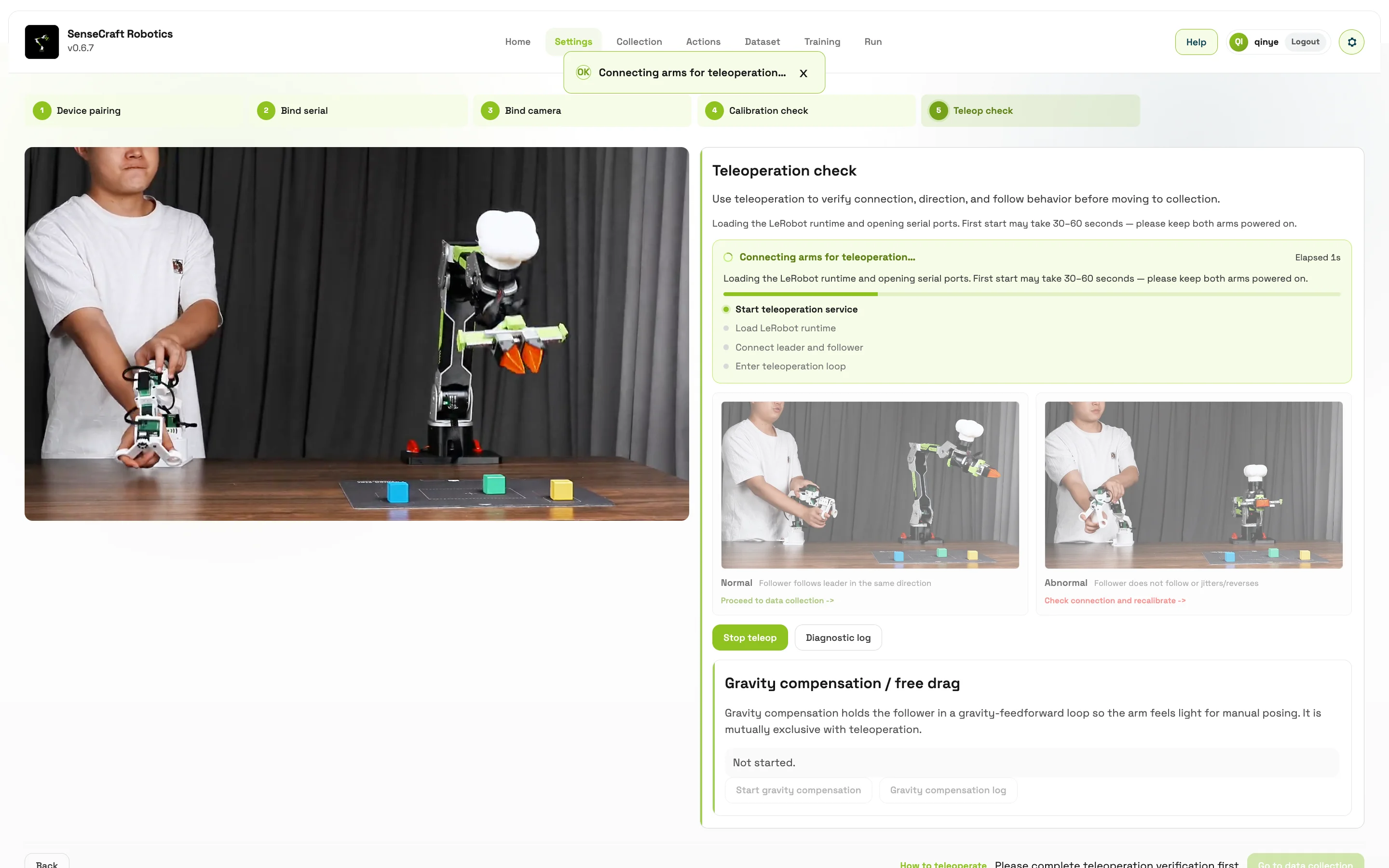
Advanced features:
- Gravity compensation / free drag: available for B601 DM follower arms. It makes the robotic arm lighter to drag and position by using gravity feedforward.
- Gravity compensation and teleoperation are mutually exclusive. Only one control loop can run at a time.